|
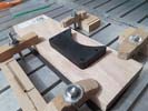
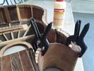
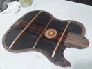
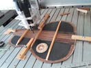
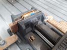
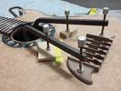
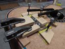
My best bet for clamping this unit while machining was to establish the four counter-bored attachment holes and use them as a means to secure the unit. It's a fairly complex machining task using 3 different cutters.
|
Left: I have the four adjustment holes drilled and counterbored and I am using those to lock the pickup cover down onto a wood base so that I can get the inlay machining done. |
|
|
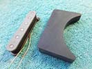
Happy to have the pickup glued together and I also cut and trimmed the additional top material back flush with the sides. I'll do a little sanding to reduce the top plate thickness and will then be ready to machine the inlay recesses.
|
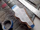
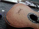
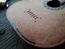
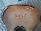
Left: Another step forward - top plate is attached and I have trimmed the extra material off around the edges. I now want to get the top plate sanded slightly thinner and get it ready for inlay work. Right: I'm in the process of programming the machining of the artwork that will exist on the top surface of the neck pickup. |
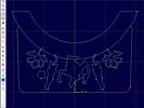
I'm busy with the programming of a couple of different tools I will use on the CNC machine to establish the recesses for the inlay on the top surface of the pickup.
|
|
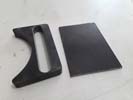
Got the top plate machined to a rough thinkness - next I will drum sand it thinner and glue it to the base piece and trim up all the edges. That will give me a complete pickup holder on which I can start the fancy shell inlay process. Will update as I move forward. Guitar is basically done except for this addition!!!!!.
|
Left: This photo is just here to show the two component pieces of the pickup. I'm going to sand the top plate down thinner and attach it to the base and clean up the edges. Then I can start the inlay! Right: Now gluing the top plate onto the body of the pickup assembly. Once this has set I'll cut and trim and get it ready for inlay work! |
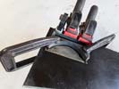
I'm using very strong adhesive to lock these twp components together. Once set - I'll trim and sand the edges flush. Then I may need to slightly reduce top plate thickness. After that I will cut the recesses for all the inlay pieces.
|
|
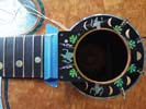
I created some new artwork for the top of the pickup with a new werewolf. Might as well use that surface to keep the theme of the guitar going. Also adding a border inlay to match the soundhole trim to make everything work visually.
|
Left: Since I am doing a lot of creative work to add this pickup I wanted to enhance the inlay a little by adding the features shown in this picture. Keep the theme going!!! Right: Not the most exciting photo but it shows me machining some black material down so that I can prep it for the top of the pickup! |
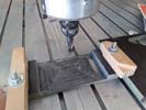
I have to machine this black material down fairly thin, then drum sand it and polish it. I will be gluing it to the top of our pickup body piece and then working on all that fancy inlay work.
|
|
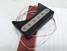
I have the pickup and the pickup body assembled and I now have to create a very intricate top piece with shell inlay that will match the inlay at the top end of the fingerboard.
|
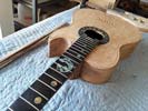
Left: The actual pickup is taking shape - I have the coil assembly fitted into the body and I am now working on the fancy inlayed top piece! Right: Just wanted to show the pickup assembly in its location on the end of the neck of the bass. It will be neatly located after the 21st fret (which will remain playable. |
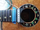
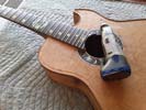
This is just a quick photo of the lower portion of the pickup assembly to show its location relative to the neck and soundhole. It will of course have a top plate .
|
|
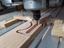
I'm busy machining a test pickup cover so that I can make any necessary adjustments to the final design. There are a few unknowns so this is definitely the safest way to go!
|
Left: I'm doing a test cut of the pickup body uding a spare piece of oak - the actual body will be black material but this will let me test and make adjustments if necessary! Right: This is a picture of the pickup body right after I took it off the CNC. I will be making a top for it with all the matching inlay work included - should look cool! |
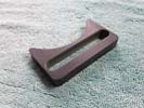
The test piece allowed me to make a vew very minor adjustments and I went ahead and machined a final body for the pickup. This material will be solid black like the fingerboard and I will add a black (probably ebony) top to it which will include all the matching inlay. Should be a nice and very unique feature!
|
|
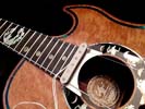
I am starting the work to assemble this neck pickup so that I can finish up this bass. I will be building a fancy engraved cover to match the existinginlay on the neck and the border of the soundhole!
|
Left: Everything on the neck pickup looks good so far and I have already started the work on the pickup cover piece into which this will fit. More info coming!!!! Right: I have programmed the body shape and recess for the pickup and will now test run the whole thing to make sure everything fits. If all is OK I will run the actual pickup body. |
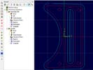
Got the programming done for the body of the neck pickup - I will get a test piece cut to check everything first. More on this soon!!
|
|
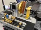
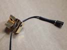
Mark put some valuable time into magnetizing the poles and winding the bobbin to create a beautiful piece of engineering that I can now use to add a second sound source to the bass!
|
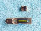
Left: Pickup has been would on Mark's fancy winding machine and it looks like we have a good useable output from the type of wire and number of winds he was able to achieve! Right: This is the end result of the custom pickup creation process and I will run out to pick this up from Mark and use it to create the custom cover. |
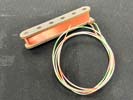
This is the end result of our custom pickup bobbin and I'm looking forward to getting it installed.
|
|
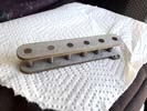
Happy to get this neck pickup bobbin assembled and I can now take this to my electronics guru and get it ready to make sound!
|
Left: This is just a little glamor shot of our neck pickup bobbin before it goes to Mark to turn it into a real pickup. He will magnetize, copper wind, seal everything and test the output! Right: Saw Mark today and gave him our pickup bobbin so that he could start on the work that will make it very custom pickup core unit! |
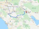
Was able to see my electronics guru to hand over the pickup bobbin and let him do his work. When he finishes it he'll be able to measure the signal output which we anticipate will be sufficient to match the bridge piezo output!
|
|
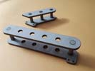
Decided to wind and test a one piece single coil pickup and also a split pair. Either option would work from an output perspective - might be a case of which fits better in the space available!
|
Left: In the interest of output and space available in the pickup area I am looking at the mutual benefits of a single and split pickup. May wind both and compare! Right: I will probably try to wind a single and a split pair and measure the signal output from each. I'm starting the cutting of the actual pickup body also! |
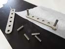
Assembling the magnets into the bobbin pieces to create the straight pickup first. I'll try both but in the end this straight version works better for leaving me a little space on the pickup assembly for height adjustment screws. I'm taking this to my electronics guru in in Palm Springs where he will magnetize the poles, wind and seal all the copper wire and test the output for me!
|
|
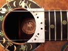
Breaking many of the traditional rules for pickup design but I really want this to be an enhancement feature of this bass and something nobody has done before! Stay tuned!!.
|
Left: After much discussion with my electronics guru I have scaled the bobbins up a little and re-sized and re-positioned the internal components. Looks like we are getting there!! Right: After a few necessary adjustments in size and geometry I have cut the bobbin blanks for the pickup. Now need to select a suitable magnet length and assemble! |
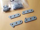
Bobbin blanks have been cut and we're fairly sure they will accommodate enough copper windings to yield the output we are looking for. I have magnets in various lengths so I am going to use the longest ones the recess at the neck end will permit and we'll go from there.
|
|
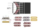
This is my scale vector drawing of one of the options for the neck pickup geometry and assembly. We're probably going to cut and assemble a set, and test wind so that we can measure th eresulting output. We have ways to calculate it based on wire size, magnets, height, width, length and number of coil windings but I'd rather know for sure.
|
Left: While working on some of the other areas of the bass I have also been working in the vecto files that will determine the actual size and shape of the pickup components! Right: I'm now test cutting the bobbins on the laser. I'm consulting with my electronics guru on bobbin size, height and output levels. |
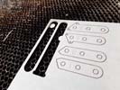
IThis is me cutting a test set which we can assemble and wind with copper. That way we can tell if we're happy with the signal output.
|
|
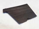
This is a piece of the same Ebony that I used for the neck of the bass. I am going to use it to create the "body" of the neck pickup!!!.
|
Left: I have some of the actual neck fingerboard material left which I plan to use to create the top and body of the pickup itself so that have a nice match with the wood already on the instrument! Right: I have a nice clean piece of vulcanized fiber for the pickup bobbins. I used the laser to cut test pieces. Just received new magnets! |
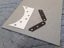
I have a nice piece of vulcanized fiber which I will laser cut to create the four bobbin pieces. I bought a selection of magnet poles in different lengths so that I have some choice in the height of the assembled bobbins before winding is done. Will test these for size and fit and if all is good will cut the final pieces.
|
|
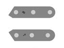
After creating some detailed scale drawings I made an accurate vector file of the two bobbins that will be part of this pickup assembly.
|
Left: These are the two pickup bobbins based on string spacing and available space in the pickup area. I will move on now to cutting the flatwork and assembling with magnets. Right: I created a vector file for the shape and pole locations of the pickup. Cut it on the laser. Just using that right now to verify final sizes and positions! |
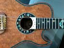
I used the laser to accurately cut a representative shape for the pickup dimensions and pole locations. Will use that to addjust & create the actual pickup.
|
|
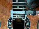
I need to give Mark an accurately dimensioned drawing of the pickup structure and dimensions so he can calculate the required copper coil windings. We want a nice balance with the system in the bridge saddles. .
|
Left: To get this pickup done I first need an accurate scale drawing. The distance between the outer strings at the pickup location is very important. More updates coming! Right: I don't want to create a big or distracting pickup shape so my plan is a very custom 2-coil assembly that will give us room to add sufficient copper winding! |
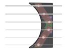
This is a better plan for a compact neck pickup and still allows me to create a discrete but artistic and functional element to the instrument. At the same time it gives me a little extra space to guarantee adequate copper winding and signal output!
|
|
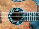
Lots of creative processing based on the ddition of a second sound source has come close to giving us a usable solution. Based on the signal strength of the pickup saddle piezos I have found out that standard acoustic sensor pickups have nowhere near the adequate signal strength to be successfully blended. Everyone (manufacturers and electronics experts) have told me the best complimentary sound source with blendable power is a standard magnetic pickup. I had an initial vision of having to plant a big square pickup in the middle of our fancy soundhole, but after some careful thought and analysis I think we can make a magnetic pickup that will blend artistically, and sound-wise, into the whole plan.
|
Left: Through some helpful dialogue with my electronics guy and my customer we are looking at creating a very custom neck pickup with matching artwork to blend into the existing design! Right: This is a rough artist's impression of the pickup showing the visible artwork on the top surface and the pickup coil itself underneath. |
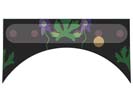
I'm still working with Mark on physical sizes and required amount of copper wire wrapping and stuff like that. Based on some info he will be giving me I will then be able to draw up a final sized reference file and get things rolling. I'll probably make the pickup frame itself with the magnets first and get that out to Mark for winding. In the meantime I am collecting ebony and the shell for the inlay.
|
|
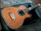
I was able to get the set of Kalium strings on the instrument and it looks very impressive strung up! I have several adjustments to make now to optimize the actual set up of the neck, bridge and nut but so far so good.
|
Left: Strings are now on the bass. This gives me and opportunity to work on the various adjustments that affect the playability of the bass. Looks great with the strings on! Right: Today I chose to take this bass out to my trusted electronics expert since the only thing that I need to do is establish the BEST secondary sound source!!! |

Took a trip out to the desert to establish the best strategy for the second sound source on this bass. This bass currently has the best signal producing system available for electronic sound. My challenge has been finding a secondary sound source to give my customer two signal source options on this bass rather than just one. Mark and I will be working on the most compatible system that will blend well with the piezo saddles in place and which will provide an unique second onboard option for the player. Updates SOON!
|
|
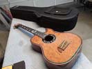
I ordered a Gator GL-AC BASS Lightweight case which is a good physical fit fior this bass and is strong but lightweight too! A bit more expensive than your average case but great quality and protection.
|
Left: I got a very nice case for this bass - lightweight but very strong, good protection and most importantly a good fit for the instrument shape and size! Right: Lots happening - finishing some surfaces in the soundhole, working with GraphTech and others to optimize sound options, getting ready to put strings on this beast! |
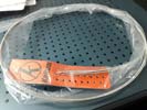
This is my custom set of Kalium strings that I will be putting on this bass.
|
|
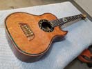
The bass looks great with its bridge assembly complete! That was hard work and now I can move on to other final tasks..
|
Left: Got the whole bridge assembly completed! Very happy about that and now I am ready to put strings on and I'm also doing some homework on the 2nd sound source and related controls. Right: The good folks at GraphTech gave me some suggestions on blending a second sound input with the ABM piezo saddles I am using. |

The technical support people at GraphTech got back to me with some helpful information about how to successfully add a second sound source to the GraphTech saddle output and balance everything so that it all works together. Will update more on this soon.
|
|
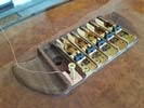
Only one more bridge/saddle/ground/piezo assembly to go and this area will be done! I will test with regular strings on although I have a specal set on order.
|
Left: Five out of 6 bridge assemblies are now in the instrument and I am almost done with the last one. Quite a task but close to done. Can test with strings soon. Right: My apologies - I didn't foresee this but in order for the smaller gage saddles to travel forward a little extra distance I have to machine a channel for the wires!!! |
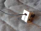
The smaller three string saddles have to be closer to nominal scale length, and in order to clear the forward screws of the bridge units I have to machine a small channel for the piezo wires!!!!.
|
|
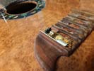
Working on the common grounding of the 6 bridge assemblies so that I can get them permanently installed!
|
Left: The task here is adding copper shielding and copper wire to the six recesses so that we are able to ground all six of the bridge assemblies. First one done! Right: The assembly, grounding and installation of these units has been quite a lot of work, but I have found a system that will yield good results. Will update when done! |
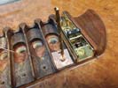
I had to do some modifications to achieve good solid grounding and had to buy slightly different retaining screws to make it all work. I'm now repeating that process through th eremaining five bridge assemblies!
|
|
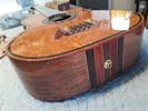
Installing a strap button / output combination unit on the back of the instrument. All the gold hardware looks good together!
|
Left: Adding a nice gold 1/4 inch output/strap button to the back of the instrument. Also locating a soundhole based mixing unit for the two sound sources on the bridge. Right: This photo is just to show that I am working on creating a common ground for each of the bridge units, and running the piezo wiring through to the body interior. |
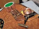
Each bridge unit needs to be grounded to the system, each piezo saddle has a cable with a connector plug that needs to run into the body cavity, and then the bridge is then secured in two places (front and back).
|
|
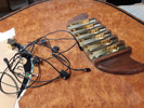
Working on the six bridge assemblies. Each one has a saddle and a piezo insert with a wire that needs to be fed through to the interior chamber if the instrument. Bridge units will also need to be grounded.
|
Left: Working on the bridge assembly. I have piezo saddle inserts to set up in each of the bridge pieces and have to run the wiring through to the interior of the bass body. Right: Doing some final work along the upper and lower edges of the fingerboard where the finish meets the frets. Very necessary work but almost done. |

Making sure all the finish build-up is removed from the ends of the frets which is quite a time-consuming job. Almost done though.
|
|
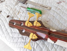
Getting the six tuners installed one at a time making sure they are all seated properly.
|
Left: Doing the final install of the tuners on the headstock. Making sure each one of them fits comfortably without any strain on the tuner of the surrounding finish. Right: Tuners now part of the instrument and they look really good on the headstock. I will now be working on sides of fingerboard and the installation of bridge assemblies. |

All 6 tuners are now installed on the headstock of the bass. Look great.
|
|
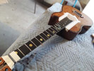
I managed to get all that masking and hardened spray removed but my next task is just as important. I need to remove finish from the ends of the frets otherwise over time the frets could compromise the finish due to expansion and contraction due to temperature.
|
Left: I was able to remove the masking from the fingerboard with minimal damage to the finish. Glad that's done. I need to file all the fret ends to remove overspray! Right: I'm almost done cutting the string slots into the nut of the instrument. I can't do the final work until the strings are on. Installing tuners next. |
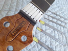
String slots are established in the nut. Will do final depth adjustments when strings are on. Will get thuners on next and then the individual bridge assemblies.
|
|
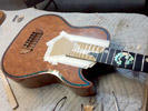
You would think this would be a relatively easy job but it hasn't been. I have to release it along the sides and break off small pieces as I go. Once that's all done I will have a lot of cleanup. Getting there.
|
Left: The finisher had to mask off the fingerboard in order to get the finish applied, I'm now working to get the masking (with finish applied to it) off, without damaging anything! Right: Fitting the nut into place and also getting ready to cut the string slots in the nut. Used the laser to create a custom template to establish spacing. |
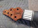
Nut has been installed and I am getting ready to establish the six string slots.
|
|
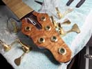
Working on getting the tuners shafts to fit back into the holes by carefully removing finishing overspray.
|
Left: I'm getting ready to fit the six Hipshot tuners and just cleaning out resin finish from the holes so that the hardware will fit. These will go on soon. Right: I'm working on placement of the screw holes so that all the tuners will be at the same angle (approx. 90 degree) relative to the centerline of the neck. |
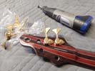
Need to drill holes for the screws on the backs of the tuners to establish their angular positions.
|
|
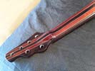
This is what the back of the neck looks like with that nice gloss finish applied. Colors of the woods look really nice!.
|
Left: This is the finish on the neck after the epoxy resin coating was applied. Colors of the woods look great and I am looking forward to getting thigs assembled! Right: I love the color and the grain on the back of the bass. This is definitely a very unusual instrument! Getting to work on the areas I need to clean up for assembly. |
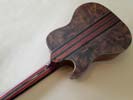
Back of the instrument body has great color and wood grain. Looks very classy!!!.
|
|
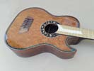
Gret to get this beast to finishing which means we are close to getting it done! Can't wait to see it!.
|
Left: Bass off to finishing today and I know it will end up looking spectacular! I'll be updating on its progress and also on the hardware/strings/wiring etc that I will be doing as soon as it's done. Right: Back from finishing this is a shot of the instrument body with a very nice gloss finish all over bringing out the beautiful wood colors! |
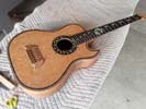
Back from finishing and overall looks great. I noticed 3 areas where I want to resolve local finish on the wood but will do some pre-assembly work first!.
|
|
Bass ready for finishing and I've got it all down to a nice sooth finish!.
|
Left: Finally done with sanding and I'm just about ready to take this bass to finishing and I'll probably do that tomorrow. I'm very much looking forward to seeing it when that process is done. Right: This is a back view - all that wood grain front and back should look awesome with the final surface finish applied!. |
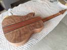
Another view of the bass as it gets prepped for the finishing process.
|
|
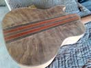
Fairly lengthy process of sanding all surfaces down to a nice smooth finish suitable for the application of the finishing. I have also been refining the thickness and shape of the back of the neck.
|
Left: Sanding the back and sides with medium sandpaper - almost ready to move onto the smooth stuff. It takes hours to get everything just right but definitely worth the effort. Right: After many hours sanding the surfaces are ready for finishing. I'm doing a quick fret dress along the fingerboard edges before the finishing process. |
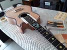
Neck is shaped and thicknessed, body is sanded and I'm dressing the fret ends before this instrument heads off to finishing..
|
|
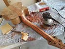
Not an easy job carving up next to the body, One wrong move and I could nick the neighboring surfces so I am being super careful. Resorting to hand tools in some areas.
|
Left: Neck thickness is now good all the way up - I'm just working now on the heel so that I get it to a point where it feels good but still provides structural strength! Right: Finally got the neck thickness down to where I wanted it - not easy to do because of all the other adjacent geometry that has to be blended in perfectly!!! |
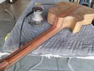
OK this took a few hours but I wanted to be sure the neck thickness, neck frofile, and all the transitions at both ends were working and complementary to each other - succeeded and now I can do some final sanding. Told my finisher I'd probably see him in a couple of days. Stay tuned for updates!.
|
|
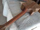
Grinding and sanding on the remaining neck area to get the body surfaces ready for finishing. Amazing how that Padouk regains its red color after sanding. The finishing should retain those beautiful colors.
|
Left: Carving and sanding the beck of the neck profile and the transition to the body. Also took the bass to my finisher to have him see it so we could establish the best finishing process. Right: More carving and some final sanding to get the neck to the optimum profile and thickness and get the best possible carved neck-to-body transition!! |
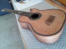
I am happy with the neck profile and transition to body and I am now busy sanding the entire instrument surface in final preparation for finishing!.
|
|
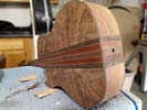
Moving along with the sanding to get the instrument ready for the finishing process. Lots of surface area to do but the woods are starting to look beautiful.
|
Left: Now busy sanding the body of this bass to get it ready for the finishing process. I have some final carving to do to the neck area and that will get the same sanding attention. Right: Now that the body is done I can finish up the neck profile and transition to the body. Rough carving with a grinding tool first, then filing then sanding! |
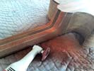
Pretty much the last phase on this beast before finsihing, is shaping the back of the neck and bringing it to the correct thickness, plus carving a comfortable transition between the neck and the body.
|
|
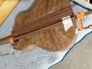
The little insert I machined fit nicely in the space so I went ahead and glued and clamped it in place.
|
Left: I fitted that little piece I machined and Iam now gluing it in place at the front end of the arm relief area. I will let that set overnight and clean it all up in the morning. Right: Sanding the whole back of the bass to blend the trim to a nice finish. I will also be sanding the sides and the top to get the whole body in pre-finish condition |
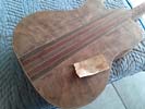
Lots of sanding going on to get the back, sides and body nicely cleaned up and smooth. I have some carving to do to the neck and neck joint area so that's next.
|
|
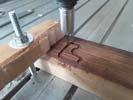
Machining the little trim piece for the sharp end of the arm relief. I will glue this in place then trim it flush to complete the back trim.
|
Left: Now cutting out the final piece of the back trim which will fit on the point of the arm relief. I'm cutting it with some extra material to facilitate clamping when gluing. Right: Just a quick shot of the trim round the back of the body as I am sanding it flush with the sides and back surface. Starting to look nice! |
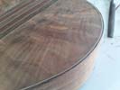
I'm working on filing and sanding the trim down flush with the back and sides of the body - looking very nice and will be done soon.
|
|
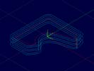
I programmed a path to cut the curve accurately and give me a little extra material on the outside for strength and to help with clemping in place.
|
Left: Only piece I have left to do is the little point on the end of the arm relief cutout. That one I have to machine out because it's way too tight of a corner to bend. Program written. Right: My material and setup are on the CNC and I'm ready to get this piece cut out. I'll carefully fit it in place and we'll be done with trim. |
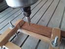
Got everything set up on the CNC sos I will get this part machined and finish up on the outer trim. After that it's pretty much carving and a lot of sanding.
|
|
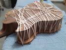
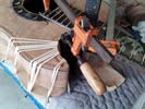
The rubber bands do a great job of securing the binding in place by applying pressure inwards and downwards. I can't think of any mechanical clamps that would work as well as the bands do for this type of joint challenge!
|
Left: Now gluing on the opposite side of the final outer binding on the back of the body. Just have the inner curve to do and a small machined insert and this will all be done! Right: Now bending and fitting the last trim are in the arm relief. It's a somwhat tighter bend but should work out fine and will soon be glued in place! |
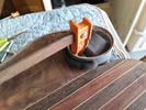
Yes it's a strange and unconventional clamping setup but I had to come up with something that applied even pressure on the whole curve.
|
|
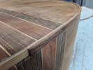
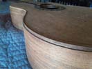
I was happy to see that the outer trim looks very nice on the instrument. Moving straight on to the other side!
|
Left: Despite the work involved I'm thinking this is going to look very nice on the finished instrument! I'm getting the second piece of outer trim ready for the same process. Right: The second side of the outer trim is successfully bent and I am setting up to get that piece glued onto the body! Watch out for a lot of rubber bands! |
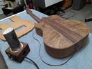
Got the second strip of outer binding bent and now will be gluing it in place onto the body.
|
|
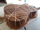
Temporary fitting of the first outer binding so that I can establish the exact length before gluing.
|
Left: I have to test the length of the side binding by attaching it to the body so that I can mark the exact end point for cutting to length. Now I can glue it on! Right: The attachment of this outer trim piece required more clamping pressure than I expected, hence the number of rubber bancs and the 3 clamps! |
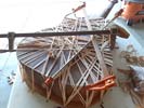
This is the first outer trim piece being glued onto the back of the body. It ended up being a bit more work-intensive than I expected but it should all work out OK. On to the other side!
|
|
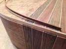
Starting on the final outer strip of binding which will allow me to consider the back of the bass finished! This material is a little but of work to bend but it will do a beautiful job completing the body trim.
|
Left: All 4 veneers attached and I am now bending the final outer trim so that I can get that glued on. I will custom machine a trim piece for the end of the lower bout! Right: I'm now setting up to do another glue session to start with the upper side trim and get that glued onto the body. Currently bending a piece for the arm relief! |
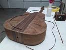
About 3/4 of the way through bending and just getting started on the gluing of the outer binding to the body. I will be very happy when that is all done!
|
|
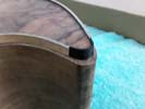
I heat bend the veneer using the shaft of my soldering iron, then carefully cut to length to get it to fit. Then glue it in. 3 more to go!.
|
Left: Working on the 4 veneer inserts on the point of the lower bout. Have to heat bend them and glue them in one at a time. Also started bending outer trim material! Right: Getting the veneers glued around the corner of the lower bout. Outer binding being bent so that I can get this all done. Will machine a custom end piece. |
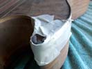
It's actually not very easy to do this - there's nothing to clamp against to hold the new veneer pieces hard up against the curve - the best way I found was using some hard sponge like material and taping that onto the joint area as hard and tight as I could to effectively apply pressure all the way around.
|
|
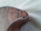
I need to add 4 layers of veneer around this sharp corner of the trim. The veneer needs to be individually bent then installed separately.
|
Left: I'm getting started on the corner of the lower horn where I need to glue in 4 veneer layers to match the trim I just installed. Right: Last stage here in this process is to bend the outer trim material and get that glued into the finished assembly. Gluing is pretty easy - but the bending part takes a bit of work to get it to fit! |
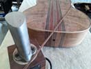
Setting up to bend the outer wood trim that will run around the edge of the body. It needs to be bent pretty close to the final shape which can be very work intensive!!.
|
|
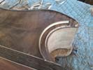
Last piece of the inner trim is now heat-bent and ready to install.
|
Left: Got the bent piece for the neck relief done and now setting up to glue that in the body. I'm making a custom trim piece by hand for the very end of the lower bout since it's too sharp to bend traditionally. Right: I am now gluing and clamping the inner binding in the small radiused area. Once this is glued in I will work on the point. |
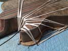
Now gluing in the curved binding in the neck relief area.
|
|
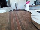
Now bending the inside binding strip for the lower side of the body. You have to be very careful and precise to get it close to the profile so that it doesn't give you clamping problems when gluing.
|
Left: Successfully heat-bent the second inner trim piece so I am prepping to get that glued onto the body. Also started the bending of the upper side outer binding strip so will update on that. Right: Back to gluing - I'm attaching the lower side of the inner binding right now. I will move on to the outer material very soon. |
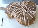
Inner section of the binding being glued onto the lower half of the body.
|
|
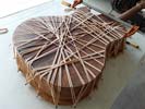
Inner strip of binding being glued in place. Not an easy job as you have to apply all the glue along the whole length then work super fast before it all starts to set.
|
Left: First strip glued, installed and clamped. Now I have to leave it a few hours for adhesive to set. Will keep this going until it's all done and will then have some serious sanding to do! Right: Results for first glue session look good - moving on. I'll probably do the same thing to the lower side of the body and then work on the final outer trim. |
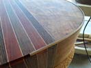
So far so good - this is the decorative piece that goes on first. I'll follow up with theouter piece to finish off all this trim work.
|
|
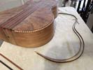
It's a slow process to get this material to conform to the shape you want. It's now close enough that I can glue it using the rubber bands for application pressure!.
|
Left: Very work-intensive because you can't bend this stuff in a hurry and it has to fit the instrument profile fairly closely. Have the two upper pieces done though!! Right: I'm clamping the first bent piece to the body so that I can accurately trim the final length. With that done I will go ahead and glue this piece into the body. |
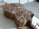
Can't cut to final length without securing the piece into its slot. I'll now trim to final length and get this section installed.
|
|
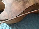
I am starting the bending process of the binding and at the same time I am creating a little matching end piece for the point on the lower bout - simirar to what I did on the front. Can't wait to get this done - will post more!.
|
Left: This is the combination binding I will be installing which matches well with the opposite side of the body. I'm bending this material to very close to the instrument profile! Right: I'm bending thebinding material so that it is close to the shape of the body perimeter. Once that's done I will glue everything in place! |
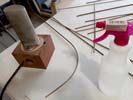
Working on beinding the two pieces of binding that will wrap around the body perimeter.
|
|
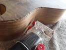
I tried out the router carefully on some spare material to see how the cut came out. Seemed perfectly good so I tried the same cut on the instrument body and so far everything looks fine so I am going to run this slot all the way round the body so that I can get the binding started!!!.
|
Left: Initial cutting with the router looks promising so I am going to proceed all the way around the body and create a nice recess for the binding on the back perimeter! Right: The router cut for the binding has been completed all the way around the body. I have a little manual shaping at both ends and at the end of the horn. |
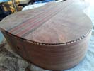
Slot for binding done - I had to be very careful with the router not to let it slip from the base and make an accidental cut! All good so far and just have some manual finihsing touches at the two ends and rounding off at the point of the lower bout.
|
|
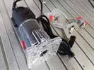
I'll be doing some pretty precise routing around the back of the body so I bought a new router to make this operation as predictable and easy as possible.
|
Left: I ran out and bought a new mini-router because I wanted to make sure I could successfully and cleanly establish the back binding work. Getting set up already! Right: I got hold of the materials I want to use for the binding around the back Have my heat bender ready. I will be grinding a small channel round the perimeter. |
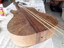
I'm pretty much ready to cut a little binding channel around the perimeter of the back plate. Have my heat bender ready along with glue and clamps etc.
|
|
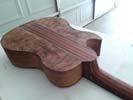
Took all the clamping materials off the assembly and it looks like we achieved a good solid joint all the way around the back plate. Now will do some cleanup around the perimeter and get things ready for binding around the outer edge.
|
Left: Looks like we have a good solid joint between the body and the back plate. My next task is to remove overlap material all the way around and prepare for some binding around the perimeter. Right: I carefully ground and filed and sanded the edges of the back plate flush with the sides so that I have a nice even surface for binding. |
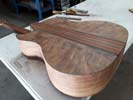
The back plate edges are now all flush or just behind the edges of the body. This is very important for me when I start the binding process.
|
|
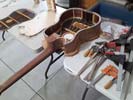
Spent part of the day making sure I had everything I need on hand before I start. Once I get it all clamped it will stay that way overnight.
|
Left: OK - everything is laid out and I'm ready to set this job started. I've mocked up the whole thing and it seems ok so I am going to apply the glue and get it all clamped down. Right: I spent some time today working like a madman before the glue got too tacky to get everything tightly clamped together. So far so good though. |
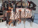
Got everything glued and then clamped together. I used rubber bands to partially clamp and hold the plate in position and followed up with the use of other mechanical clamps. It really looks like everything is well compressed together. Will unclamp everthing in the morning and we'll know more!.
|
|
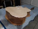
I cut a clamping board for the bottom panel and it has a pattern of screws inserted on the edges which I will use for applying clamping presure. I's a big job but half the work is already done!!
|
Left: I built another clamping plate so that I would have an easier time clamping and applying the rubber tensioning bands after gluing. Ready to get this done! Right: As another safety measure I cut a piece of heavy card material to protect the to surface of the body from the fixture surface. Don't want that area damaged. |
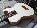
I wanted to put a protective material between the fixture surface and the actual top of the instrument since we will be applying a good amount of pressure.
|
|
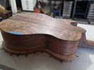
Everything looks promising for the back attachment setup. I expect to have a combination of rubber bands and standard clamps to make this all happen.
|
Left: Test fitting the back to make sure joint contact and positioning is correct. I will have a fairly elaborate setup to make this part of the assembly happen so getting part of the shop ready! Right: This is the body and the back plate right before they were glued together. A lot of work went into the preparation but it will all be worth it! |
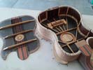
Both parts of the final body assembly are ready to go together. The gluing process is complicated from a clamping point of view. Will post pictures.
|
|
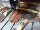
I had to machine the back of the back plate to match the mating surface on the body. Looks like all mating surfaces are now prepared for assembly.
|
Left: One more machining operation to make everything fit together. Building an acoustic bass is a very detailed project, but everything has gone well. Right: All the required surfaces have now been machined. I will clean up this back plate and get it ready for assembly. Once the back is on I will be doing some binding around the edges! |
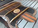
Moving on now to assembly of the back plate. Lots of tooling involved for that operation!!!.
|
|
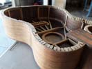
I'm happy with the machining results for the joint face for the back panel. Just need to re-assemble my CNC table! Photos soon of the back plate being attached..
|
Left: This is the bass body with a really nice mathematically flat machined joint surface around the back of the body. I have tools ready for attaching back to body! Right: I'm now machining some of the extra core material flush on the actual back panel itself. Had to do some careful measurements but working out fine. |
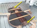
The yellow arrows show where I have to add joint surfaces at the front and the back of the inner surface of the back plate. This yields a 360 degree flat wood-to-wood joint surface for gluing.
|
|
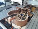
I wanted to add a few additional joint support pieces as I have the back plate ready to be attached.
|
Left: While I am working on the positioning and marking of the output piece - I am also adding a few additional inserts for the joint to the upcoming back plate assembly to achieve 360 degree joint surfaces. Right: I put the whole body up on the CNC so that I could generate a nice flat joint surface all the way around. Tough setup!!! |
This was a complicated setup as I had to remove some of the CNC table to achieve the required height for the cutter. Successfully managed to get the whole back joint surface accurately leveled.
|
|
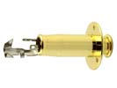
I needed a good sturdy stap button assembly combined with the standard 1/4 inch jack output. This one should do the trick!.
|
Left: I needed a good sturdy quality made jack socket and strap button combination in gold plate. This one is a Gotoh and should do a good job for both purposes. Right: Well - that was fast - just received the strap button / jack socket combination in the mail. I will now go get that set up on the binstrument body! |
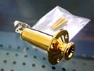
This looks like a really nice quality piece of hardware! I'll get a hole set up in the body to accept this output socket!
|
|
Got the decorative plate installed and applied some sealer before I move to attaching the back plate.
|
Left: Fixed the insert into the recess and cleaned up the surrounding area then applied sealer. I'll probably re-seal during the process of attaching back. Right: This is what the insert looks like through the top hole of the instrument - I'm currently doing the setup to get the back plate glues onto the rest of the body. |
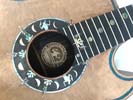
I wanted to post a quick photo of the view through the soundhole - should be nice when I get that back plate on. Will update soon.
|
|
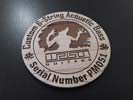
Nice to be able to continute the theme of the instrument on the plaque inside the body. Will be redy for finishing pretty soon!.
|
Left: I found a very nice piece of spalted maple that gives me better contrast for this plate. I will now cut a matching recess for it in the back plate and get it glued in! Right: Now ready to cut a recess so that I can glue the insert into the backplate material. Once that's done the back goes on and instrument will be one complete piece! |
Just about to cut a recess for the plaque I recently made. Had to wait till today to get this operation done due to inclement weather and the threat of power cuts.
|
|
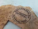
I'm looking for the right piece of wood so that I can cut something like this and insert it into a recess in the back plate so you can see it through the soundhole.
|
Left: I thought it might be nice to insert an instrument identity on the inside of the back plate under the soundhole. This is just a test but it would look something like this! Right: Or maybe something like this to keep the "theme" going! Once I find the right piece of wood I'll cut it and get it installed - should look nice! |

There's so much nice artwork on this guitar it would be a shame not to use it in the insert!.
|
|
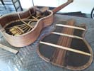
Been very busy on the prepration of the joint surfaces involved in attaching the back plate. It will be a fairly complicated gluing setup but should all work out fine.
|
Left: I have marked and trimmed the outer edge of the back panel and have als been sanding the joint surfaces of the body to ensure flat surfaces that will bond well together. Right: Got all my gluing products and fixtures out so that I can safely set up the process of attaching the back plate to the rest of the body! |
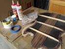
I actually had to run out today and buy more rubber bands that are shown in the picture because I want to guarantee good and even clamping pressure all around the assembly when I set the gluing process up.
|
|
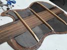
Cutting the Carbon Fiber sections was slow and tricky job but now have them all ready for bonding to the inner surface of the back plate.
|
Left: I used the paper templates to cut the carbon fiber sections that will be applied to the back. Slow and difficult work and glad it's at least cut! Next challenge is attaching it. Right: Mixed more epoxy and spent the morning getting about half of the carbon fiber sections glued down. I will wait till this lot cures and then do the rest. |
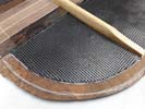
This job will tolerate no errors - the CF material is fairly delicate when cut so it needs to be handles very carefully. I applied a base coat on the sealed wood, carefully placed the CF on that area, smoothed in down across the whole surface, used a special little tool to seal the edges, then applied more adhesive to seal everything from the top. I will ceck it on a hourly basis to make sure it all sets properly.
|
|
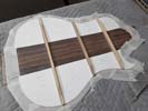
I now have templates for the carbon fiber areas so that they do their work but at the same time leave the perimeter of the back plate free and clear to attach direcly onto the side bracing pieces.
|
Left: It's a little complcated - I had to make templates for the CF so that the areas that are covered do not interfere with the wood-to-wood joint areas that I will depend on to secure the back plate! Right: I created a thin coating of my very strong epoxy on inside surfaces of the wood. This will prevent any chance of bleed-through. |
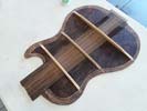
The application of the carbon fiber material with the epoxy requires a comparatively heavy application. In order to guarantee a sealed surface before I do that I applied a very thin coating of the same epoxy on the inner wood surfaces.
|
|
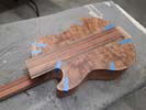
Spent tome time carefully trimming the ends of the bracing on the inner side of the back plate assembly so that the back fits snugly in exactly the right location.
|
Left: Back plate has been aligned and positioned relative to the wood laminates on the body. I have marked outer and inner perimeters for trimming and carbon fiber, and have trimmed inner bracing to achieve a clean fit. Right: I am now ready to cut all the pieces of carbon fiber that will fit in the inner surface of the back plate. |
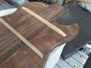
I will now be trimming the edges of the back plate and carefully cutting the carbon fiber material which will be glued onto the inner surfaces of the back plate.
|
|
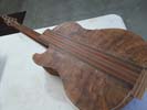
The fit between the body and the back plate has to be close to perfect so it's a case of doing a little at a time and testing. Also will have to line the inside spaces with carbon fiber like we did on the top plate!
|
Left: I drilled wiring holes for bridge saddle wires and now finishing up on the fit between body & back plate. Once that's done I'll prep for gluing it on! Right: Got the bracing on inside of the back plate cut & carved to make it fit nicely in the location I wanted. Marked outside for trimming. Now need to cut and add some Carbon Fiber! |
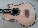
Making progress - back is pretty much fitted to body to create a nice clean and very important joint connection all the way around the body. I'll do a little trimming on the outside nd finish the outer edge after gluing. Now have to cut and attach the carbon fiber material.
|
|
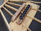
I got the other half of the Hipshot hardware installed in the under-side of the bridge. Now I can say that the bridge saddles will be very securely attached!!! Phew!.
|
Left: Holes drilled and string retainer hardware tested and installed. I just have to drill six little holes for the piezo wires and this time-consuming jobe is done!!!!! Right: This photo shows the drstribution of the bridge saddles based on intonation adjustment. I'm using this pattern to establish piezo wiring holes through body top. |
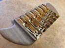
I'm preparing to drill the holes for the piezo wiring and in doing to wanted to make sure they were placed relatively close to the saddle locations when intonated.
|
|
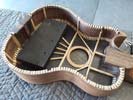
I am using a couple of metal weights as a clamping setup to secure a piece of wood to the bridge assembly. When it;s done I will have a strong system to securely attach the bridge assemblies.
|
Left: I am now gluing a piece of wood under the bridge assembly through which I can run the bolts retaining the saddles. It's under the metal weights in the photo!! Right: Gluing of retaining screw block very successful and now I can move on. Will drill 6 holes for the retaining screws and start working on attachment of back plate! |
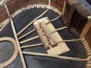
OK - got the extra block attached for the retaining screws for the bridge units. Moving on now to some drilling and then fitting and gluing back panel!.
|
|
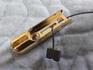
Piezo wire can now be passed through the bridge unit. Has to be a slot rather than just a hole to permit intonation adjustments for the string saddles.
|
Left: So far so good - I have cut the slot in the base of the bridge units and this allows the piezo connector and wires to pass through. Now need to do similar on the saddle. Right: The machining of the slot into the saddle was actually a harder task to accomplish but after a hard morning's work I got it done!! |
Elongated hole/slot now established in the saddles for the piezo wires. Has to be big enough to let the connector end pass through but small enough not to interfere with the saddle height adjustment screws.
|
|
I need to machine the bridge body with a slot for the piezo wire. I also have to establish a hole and slot through the saddle assembly. Will update on progress.
|
Left: I am now setting up to machine two different components. One slot (yellow) in the saddle bodies and a hole/slot combo in the saddle bases. Right: I calculated carefully where the holes and slots needed to be in both components and I am now set up on my machine to modify these six individual bridges. |
Ready to go on a setup to drill wo holes and two slots for the piezo cabling.
|
|
I took care of the details inside the bass below the bridge that allow for the installation of the bridge units and connections for the piezo signal wiring. Now I need to do a final fit with the back, apply the carbon fiber support and trim it to pretty much final size.
|
Left: Got the bottom of the bridge prepped for piezo wires, grounding and the mechanical attachment of the ABM bridge units. Now ready to fit and attach back. Right: Next thing I am doing is cutting a machined slot in the bottom of each of the bridge units so that the Piezo wires can travel from the saddles through into the body. |
Want to get this task done while I am busy attaching the back plate tho the rest of the body. I'll be busy with that but the bass will be capable of making sound!!.
|
|
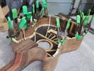
More bracing pieces being glued in place. They will create a nice solid surface onto which the back plate will be glued.
|
Left: I get around 10 bracing pieces attached and clamped at a time, wait till the glue sets and do it all again. We're getting there and so far it's all working out well! Right: OK we got all the bracing glued in for the bottom of the body. I'll make sure it's all level then check the locking mechanism and wiring for the string retainers. |
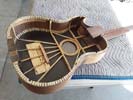
Great to have all these bracing pieces secured in place. I'll be doig a little interior work while I still have good direct access, then I will get the back glued on!
|
|
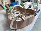
Got started on the bracing pattern. Will probably take a day or two to complete this but will provide me with a good solid surface into which we will glue the back panel.
|
Left: Got started on the process of gluing in the bracing pieces to the sides of the instrument body. Will keep working on this until we have a complete new surface! Right: Busy gluing support bracing pieces all the way around bottom edge of body. When that's done I'll check piezo wiring under bridge and get the back glued on!! |
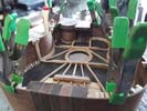
Should be done with these little bracing pieces soon. I'll check wiring channels for piezo bridge saddles and once that's all set the back can go on.
|
|
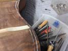
Refining the fit of the back panel before I start installing the bracing pieces!.
|
Left: Working on each of the bracing ends so that they all fit the inner profile of the body sides and yield a nice alignment to the neck heel and the back plate of the body. Right: Setting up for the addition of the back bracing pieces. Need to spend a day or two clamping and gluing these in place but can then attach the back! |
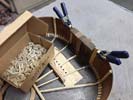
I'll have multiple clamps all working at the same time. Will get all these glued in and then will carefully level the resulting surface so that we have a nice fit with the back plate.
|
|
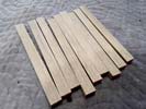
I have been busy on the drum sander creating the finish cross section for the bracing pieces. Looking good.
|
Left: I have now sanded width and height of these pieces to the required dimensions. Next I will machine an angle to finish the geometry and get them all cut up ready for assembly! Right: These are the first 20 or so bracing pieces which are carefully sized to do a good job of supporting the internal structure inside the body! |
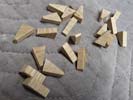
These are the first few bracing pieces I cut - they will do a great job of supporting the joint of the back plate to the sides of the body.
|
|
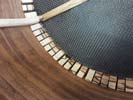
I will be making a set of bracing pieces in order to attach the bck plate to the body. Then we can put this beast together!.
|
Left: I can't use standartd guitar bracing in this instrument because it's a bass body and needs a little more physical support around the back/body joints. I make the pieces Myself! Right: I had some White Limba in stock which will work perfectly for the bracing - got it all rough sawn and I will now run it through the drum sander. |
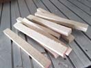
Got the bracing material all sawn up - will now sand it to final dimensions and crete my custom bracing!.
|
|
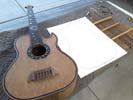
Created a template to help with the task of getting the back to fit the body profile.
|
Left: I created a template of the body shape so that it could help me center and plan out the areas that need to be trimmed. Tricky work but it will be worth it! Right: I received the package of Piezo Saddles and some other related parts from GraphTech. These will be loaded into the Hipshot bridges as our sound source! |
Very happy to receive the piezo saddle kit from GraphTech. There will be some machining work on the bridge units to install these but will be worth it.
|
|
Now working on the fairly complex fit between body and back plate to get a nice tight and secure joint all the way round. Good bit of precise woodworking to get that done then I have to apply carbon fiber to the inner surfaces before I fit everything together.
|
Left: Now looking at the marriage between the body of the instrument and the back plate. I have some material to trim off to achieve a good fit so I will be starting on that. Right: This bass has a beautiful back which which will look even more amazing after sanding. I'm cleaning up the surfaces and working on the fit. |
This back will be carefully sanded and I will be shaping the internal bracing for a good fit. Once that's done I will trim the perimeter.
|
|
Want to get the neck to the final thickness and create a comfortable transition at the body.
|
Left: I now need to finalize the thickness of the neck and the geometry of the neck-to-body transition. I'm doing some of the rough shaping work first with a grinding tool and will move on to sanding. Right: I'm now getting hold of the very best set of quality piezo saddles for this project from GraphTech in Canada. |

GraphTech make great products that are compatible with the Hipshot bridges we are using.
|
|
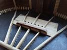
The material for the Hipshot tuner attachment has been carefully added to the structure below the bridge.
|
Left: The support piece has now been successfully glued into the base of the bridge. This will allow for a very solid connections for the Hipshot saddles. Right: I'm now looking at the mechanical requirements for feeding piezo wires through from these bridges to the inside of the instrument. Will post photos of the solution!!! |
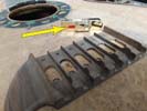
I will have to machine a hole for the saddle piezo wires under each saddle.
|
|
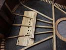
It may end up being a little smaller than shown and will blend nicely with the rest of the interior bridge support.
|
Left: Based on the placement of the Hipshot retaining screws I am adding a piece of support material under the bridge. Will have to machine it to seat over the bracing. Right: I machined angles slots into the insert for the bottom of the bridge support and I will now get that solidly glued into the instrument. |
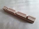
This should work great for the ABM support screws. I used a wood that's not too dense so that it doesn't add any weight.
|
|
Instrument looks good with the wooden part of the bridge attached. The ABM string retainers/saddles will be securely attached to this.
|
Left: Very happy to get this bridge assembly attached. It will ultimately be sending electronic piezo signals and should sound pretty good! I'll be adding attachments for the Hipshot saddles. Right: I now want to add a small piece of wood below the bridge to align with the row of screws that will hold the front of each tuner. |
I am now adding a strip of wood to the lower bridge structure that will provide a little more material for the screws on the front end of the tuners to securely lock down inside the bridge assembly.
|
|
Setting up the clamping arrangement for the bridge. Looking forwared to making this a part of the body assembly.
|
Left: Getting clamps ready for the bridge attachment. I will also use the center holes for the tuners as clamps through the bridge so I'll have plenty of clamping pressure to get a nice tight joint. Right: OMG this is one crazy glue up - took me an hour just to set it up but it is now being clamped onto the instrument top. |
This is the actual gluing setup. Had to be careful not to use too much glue to bleed out all over the place and still use enough for a nice clean solid joint. I will leave this overnight before un-clamping.
|
|
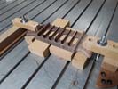
Quick operation on the CNC where I need to cut radiused slots to permit attachment of the ball ends of the strings to the AMB bridge units.
|
Left: One operation that's easier done while the bridge is separate is that I have to cut clearance slots in the back of the bridge to allow for for insertion of the ball ends of the strings. Right: Got the recesses at the back of the bridge cut and it's now ready to go on the instrument body. Wood will be darker when finished. |
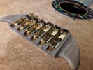
Clearance for string attachment now machined into bridge. As soon as I get all the clamps and tools assembled I will attach it to the body.
|
|
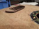
Looking forward to getting this bridge permanently attached so that I can take care of bridge unit requirements and move on to attaching the back plate.
|
Left: Test fitting the bridge and everything looks good so far. I want to get this on the body and be able to work on attachment and wiring requirements for the bridge units. Right: Before attaching to the main body of the bass I wanted to finish all the sanding on the bridge unit. Now looks ready to become part of the instrument! |
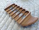
I sanded all of the bridge plate since that's a lot easier to do while the piece is separate. It's now ready to be glued onto the top of the bass.
|
|
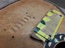
Establishing 4 holes which will add to the strength of the bridge-to-body connection when the bridge is glued on. You can imagine it will be under quite a bit of tension with 6 strings.
|
Left: I have to use my template to drill 4 blind holes in the back of the bridge for additional reinforcing pins. Once that's done the bridge can be attached to the body! Right: Adding pins to the base of the bridge to add a little extra bond with the top of the instrument. The whole surface will be glued down onto the top. |
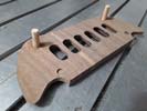
Once I attach these 4 positioning pins I will set up a fancy clamping setup to attach this bridge to the top of the body.
|
|
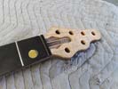
Happy with the outcome on the tuner holes. This will aloow me to finish off the headstock area and its transition to the neck profile.
|
Left: Got the holes for the tuners all drilled. I did a few careful calculations to make sure their positioning was good then drilled with pilot holes then with the full size bit from both sides. Right: Now looking at getting the bridge attached. First things is checking height alignment and if that is all OK I'll sand and attach the bridge. |
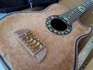
Working on making sure everything looks good for the attachment of the bridge unit.
|
|
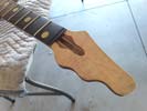
I had left a little bit of extra material around the headstock just in case it was needed - looks like I can reduce that a bit and get this area finished off.
|
Left: I can make the headstock quite a bit smaller (and lighter in weight) so I am cleaning up the profile so that I can cosider that shape complete. Tuner holes going in soon! Right: Got the headstock carved down to a smaller overall size and now I will go ahead and mark out and drill the 6 tuner holes in the headstock. |
Reduced headstock a but which helps in both size and weight. Now setting up to establish the six tuner holes.
|
|
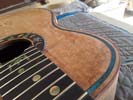
I had to fill the top surface then scrape and sand level all the way around so that I end up with a nice flat surface for final finishing. This will still be sanded but at leat the border is pretty much completed!.
|
Left: Just finishing up the inlay and filler around the border inlay so that I can move on and get the rest of this body done! Right: I'm going to install the bridge unit onto body while I have access through the back. I'm testing the fit of the Hipshot bridge units and making sure all the holes for wiring and grounding align. |
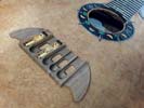
Once I have everything fitted and tested I will do some finish sanding on the bridge surfaces and get that glued onto the top of the bass.
|
|
Working on creating a good fit between body and back plate. Hoping to get the back attached pretty soon!!.
|
Left: Getting the back panel trimmed and prepared for being fitted onto th erest of the body. I'm also going to apply some of the carbon fiber cloth to the inside surfaces. Right: I'm now filling the very small vertical distance between the top of the inlay and the top of the instrument. This will be scraped and polished flush with top. |
Filling the top of the inlay with a very hard setting and clear finishing epoxy. This will ensure a very nice flat fsurface before final finishing.
|
|
This template when complete will be my guide to cutting back the bracing on the back panel to get a good fit to the sides.
|
Left: Working on the template to mark all the side and back bracing locations, plus any other features that will affect the fit of the back onto the body. This will allow me to accurately trim braces on back. Right: I am now marking the inside surface of the back plate so that I can establish the areas of overlap on teh back braces. |
The template allows me to mark where the back braces need to be shortened so that they will all fit inside the body perimeter.
|
|
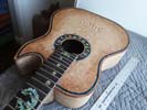
Doing the border inlay was quite a lot of work and I'm glad it's all in. Some light clear filler to do then I will fine sand the top again. Bridge will probably be installed next.
|
Left: Very happy to post that I have completed the inlay all the way around the top of the instrument. I have a little final cleanup to do to the entire top but ready to move ahead! Right: I made a template of the actual body shape which I am going to use to do some preparation work on the back plate to create a good fit. |
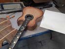
One of the next tasks is preparing the back plate for a good fit with the existing body. The paper template will make that job a lot easier.
|
|
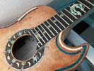
Getting the last of the perimeter shell done. Also have been sanding around the body and refining the profile of the neck.
|
Left: Working on last few pieces of shell inlay so that I can get the top all completed. The shell looks really nice round the perimeter. Bridge will be attached next. Right: Busy getting the last few pieces of edge trim inlay set into the instrument top. Everything looking really nice. Moving on to some other structural operations very soon! |
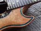
Done with the lower half and only 2 more pieces for the top half. Great to get this done and now looking forward to the next few stages.
|
|
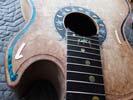
I will soon be all the way around the instrument with the shell inlay. Already tested the clear filler so that we can yield a nice flat surface.
|
Left: Now working on the last few pieces of border inlay. I have filler I will apply to level the top surface and it will be great to have this job done! Right: Cutting and installing the last few inlay pieces around the body perimeter. Also started the filling process that will yield a nice flat surface prior to the final finishing on this instrument. |
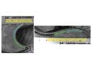
I photograph and then scale all of the cut pieces of shell in a vector drawing program and export the results to the machine that cuts the shell for me.
|
|
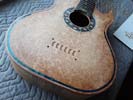
each time I have to take a photo of the next 4 inches, scale that photo in Illustrator, then carefully draw the next four inserts, save those shapes, transfer to my laser cutter, test cut on cardboard and see if the fit correctly, abjust shapes if necessary and THEN cut the actual shell!! Repeat until done!
|
Left: Got about four more inches of shell installed on my way round the perimeter of the body. I will keep this going and I am now over half way through this! Right: Got a few more pieces of inlay done around the body perimeter. Couple more sessions and I will be done and I will move on to filling and leveling the perimeter surface. |
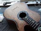
Few more inches done on the inlay. I want to get this sage fnished and get the top surface finished off.
|
|
The headstock is currently slightly oversize. I'm going to trim its perimeter down closer to my 6 string headstock template, then mark out and drill the six tuner holes..
|
Left: While I am working on the edge inlays I am also getting the headstock ready for finishing. I need to trim around the perimeter and get thetuner holes drilled. Right: Some more shell installed around the body perimeter. It's a slightly tricky process and I feel it's safe to do about 4 inserts at a time. Should look really nice though! |
Moving along with the outer shell inlay. We chose a good width for this inlay, should look good on the finished product!
|
|
Got started on the installation of the shell atound the top of the body. Should look really nice when complete.
|
Left: I installed the first few sections of shell into the groove I cut around the body perimeter. Seems like it all went pretty well so I will continue the process all the way around the body. Right: Working on getting several more inches of this edge inlay installed. I want to get this all glued in and leveled as soon as possible. |
Moving forward on the edge inlay. Once it'sall installed I will level the top surface flush.
|
|
I am testing inlay pieces for shape and fit before I cut the actual shell. Not an easy process but we will get there.
|
Left: Back on the laser where I will be cutting a lot of custom shaped shell pieces for the top perimeter inlay. Looking forward to seeing the end results! Right: I have cut out the first 4 inlay pieces and I'm checking them for fit and form. I will then proceed to all the inlay pieces and get them installed all the way around the body! |
This is what the shell looks like in the recess I cut around the perimeter of the instrument body.
|
|
I need to get the top surface around the perimeter pretty smooth before sealing the woodgrain so I am doing a lot of fine sanding.
|
Left: I'm applying a coat of sealer around the edge of the body to prepare those surfaces for the installation of the shell pieces. Doing some sanding to prep surfaces for that. Right: Body looks a lot different with the sealer applied. This is only to protect the grain as I use adhesive to secure the pieces of shell in the recess around perimeter! |
I have now sealed the wood around the slot where I will be installing the decorative shell trim. Next step will be to get all the pieces cut.
|
|
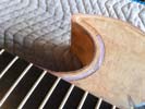
I don't want to use up or waste my final shell so I am testing with a color of similar shell that I have rarely used. Looks pretty good so I am moving forward.
|
Left: Yes it's not the final color but I wanted to cut some shell just to see how it fit into the channel as a final test. Actually pretty good so I will keepthings moving forward here. Right: While I am busy working on the perimeter inlay I am also working on other areas - in this picture I am refining the shape and size of the neck heel. |
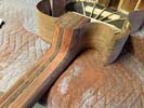
I want to minimize the heel as much as I can but still retain strangth for a6 string bass. I will keep removing material until the instrument feels right when playing the upper frets.
|
|
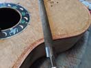
Leveling off the outer trim- thenI will sand smooth. After that I canseal and work on the perimeter inlay.
|
Left: Working around the perimeter of the top where I am leveling the outer trim material flush with the top surface of the body. I'll sand this area to finish it off. Right: First test on the inlay shapes and sizes was pretty decent - I will make some minor modifications but should be able to continue this process all around the body. |
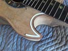
My goal is to use the largest pieces of inlay that I can while maintaining good accuracy all the way round. I will do all the individual inlay pieces this way before I commit to cutting the shell which is expensive stuff!
|
|
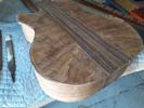
This instrument should look very impressive with the back on and the body complete. It was created purposely slightly oversize and I will be trimming it to fit accurately.
|
Left: The back plate of the body is being prepared for assembly onto the body. It is slightly oversized so that I can place it correctly and trim it flush around the existing body. Right: I am using the laser engraver to test cut some cardboard for the perimeter inlay. Once I have refined all the geometry I will cut the actual shell and get it installed. |
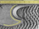
I am using carefully plotted vector paths to generate the pieces I will need to cut for inlay. I little work intensive but the best way I can think of to get reliably accurate results!.
|
|
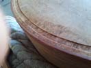
This is the slot into which I will be doing the outer inlay. I'm cleaning it all up then will apply some sealer to prevent adhesive from bleeding. Anxious to get the outer shell installed.
|
Left: This is a more close-up view of the side trim recess. I will be sealing the wood all the way around the perimeter of the top so that I cam safely glue in the shell trim. Right: Preparing the location of the bridge unit. I need to drill holes through which I will be running the piezo wires. Then I can permanently attach the bridge. |
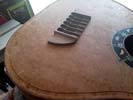
Bridge will need to be final sanded and attached before I glue the back plate on.
|
|
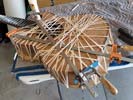
Installation of the shell trim round the body perimeter will be a tough process. I will meaure and draw out each piece, test them on other material and only cut when I am sure each component fits. Prior to all of that I have some surface sanding to do and then will treat the local area with a sealer which will prevent glue from soaking into areas of the top wood where I do not want itto go!
|
Left: I'm marking out equally divided areas into which I will be installing the shell outer trim. I will have to very carefully plan the shape and curve of each piece to fit cleanly in the perimeter slot! Right: Text and picture coming |

Installation of the shell trim round the body perimeter will be a tough process. I will meaure and draw out each piece, test them on other material and only cut when I am sure each component fits. Prior to all of that I have some surface sanding to do and then will treat the local area with a sealer which will prevent glue from soaking into areas of the top wood where I do not want itto go!
|
|
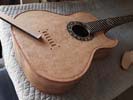
Not an easy task but it looks like everything is being held together correctly and I will now wait till the glue has set.
|
Left: After a lot of very tricky bending I got the outer trim for the upper body half close enough to the profile and finished length to go ahead and commit to attaching it to the body. Right: All the bands are now off the body and I'm busy filing the top and sides of the added trim flush with the instrument body. Looks good so far! |
Side trim now installed and I am sanding everything flush to the top and sides of the instrument body.
|
|
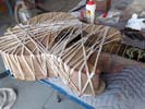
A lot of work but good to see this all happening to this instrument! I will bend and attach the upper ha;f as soon as glue dries and all these rubber bands come off.
|
Left: Gluing the edge trim onto the lower half of the body. No question - the best way to hold this on while the glue dries is by using an array of rubber bands. Right: Now bending the trim material for the top half of the body. I am also sanding the trim applied to the lower half to blend that with the body top and sides. |
Spent quite a lot of time carefully manipulating the upper trim to fit the routed recess around the body. Got it pretty close and now should be able to cut to length and repeat the gluing process.
|
|
The second-hardest piece on the outer trim is being attached to the body!.
|
Left: I have now machined a wooden piece for the tight curve around the lower horn and I am gluing that in place. Once that is done I will bend and attach two strips to complete the outer trim. Right: I have pre-bent the outer trim for the lower half of the bass. I will trim to length and glue on but need more rubber bands the right length!!! |
Ready to get the 2nd last trim piece glued on - running out to Staples to get more rubber bands!!!!.
|
|
The hardest two parts of the outer trim are the inner raduis for the neck relief area (which I am bending now) and the small radius on the very end of the lower bout which I will cut from solid material because that will be too small a radius to hope to bend.
|
Left: All the initial trim has been installed and carefully blended with the top. Now I am test bending the main border trim to see if I can bend it enough for the lower undercut! Right: Starting with the most difficult piece- this is the first component of the outer trim being glued in place. The remainder should be easier! |
Gluing the curved trim I recently bent into the inner curve of the lower body.
|
|
First layer is just a trim onto which I will attach the main outer binding.
|
Left: I'm almost done with the first phase of trim which was a veneer layer around the inner surface of the cut I made for the outer trim. Will now need my heat bending equipment!! Right: Using hand dremel tool to finish up all of the slots. There were areas where the dremel setup and the CNC simply could not get close to the body! |
Finishing up the couple of areas of the slots where the dremel fixture and the CNCcould not get too close to the body. With this done I can cut, bend and inlay the perimeter.
|
|
It has not been easy but I now have channels for binding and inlay all the way around the instrument body. I will probably do the binding next and then the shell inlay.
|
Left: All inlay/binding channels have been machined into the perimeter of the body. I am now getting ready to install the outer trim. Need to hand dremel a couple of areas first. Right: Starting on the initial gluing work for creating the outer trim around the top of the body. It should look really nice once this has all been added. |
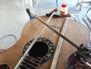
Have been doing some hand finishing work with the dremel and now getting started on the outer trim. Looking forward to seeing this!.
|
|
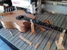
Not an easy setup and probably not an easy job to run but as long as I am very careful it should all work out.
|
Left: In order to get the edge inlays done I have to finish the two slots on each side as they near the edges of the fingerboard. Have to do that carefully on the CNC. Right: Now in the middle of cutting the ends of the slots around the lower body bout. Took me most of the day and it's not done yet! Want to make sure it's right! |
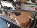
Cutting the two slots on the bottom bout has been much harder to do. I programmed it as close as I could but each slot needs manual editing of the paths to make it match the body contours.
|
|
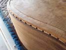
This channel had to be done extremely carefully and I am very glad that it is just about done!!!.
|
Left: Just about done with the second routing challenge for the outer binding. I will have to carefully heat bend the material that fits into this outer channel and then glue it all in with an elaborate setup! Right: I received the material for the edge binding and I will be able to install that as soon as I machine the ends of the two channels. |
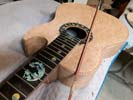
I now have a bundle of Bloodwood binding that I can fit into the outer channel. Will need heat bending and a LOT of careful clamping.
|
|
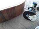
Thank goodness I have alaser cutter that allows me to manufacture my own custom tooling!.
|
Left: I had to use the laser engraver to cut a custom guide for the dremel assembly. It has now been modified and should do a good job of guiding the cutter. Right: The actual cutting on the body is pretty tricky. I'm taking it slow to avoid mistakes or problems with chipping wood due to taking too deep a cut at one time! |
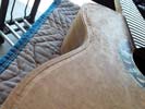
Not an easy job - I will need to do this all in several progressive cuts.
|
|
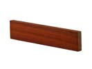
I chose bloodwood for the binding material because it will contrast beautifully with both the walnut sides of the bass and the Amboyna top.
|
Left: Just FYI - I am going to use a binding of natural wood around the top (and maybe the bottom) of the instrument. This will give it a very classy look. Right: I have also set my dremel up to cut the recess around the edge of the body for the bloodwood binding. This will create a very nicely finished edge around the bass body. |
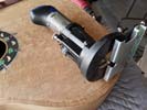
I spent some time working on this setup because I need it to cut exactly the width and depth of the binding.
|
|
The magic of this solution is that it invisibly fills any gaps between inlay and parent material and protects the inlayed surface.
|
Left: My clear filler arrived and I now have the ability to get the shell cut and inlayed and will have this magic formula to add a leveling skin for a beautiful flat inlay ready for final finishing! Right: Next task is to set body up on CNC and machine out the last parts of the body inlay recess at the ends wher the router assembly couldn't reach! |
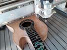
The apparatus of the router assembly did a great job of following the contour of the body but was not designed for tight curves or getting close to the two ends. Therefore I will machine these carefully on the CNC.
|
|

One of the critical components in getting a good result from inlay work is having a finishing filler that sets hard and clear. After doing a lot or research this product was recommended to me as a first class solution for what I need to do!.
|
Left: Once the shell is glued into the slots on the top I need to finish the surface with the best possible clear and hard filler. This product was highly recommended for that purpose! Right: More work going on around the neck/body joint until I feel that the size and shape is comfortable and allows easy access to the upper frets. |
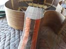
Grinding my way into the final neck-to-body transition after which I will use hand tools and sandpaper to finish up the profile surfaces.
|
|
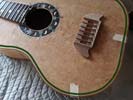
I was working on the best options for proportions on the inlay around the border. This seemed to be a nice balance based on the body shape and size.
|
Left: This is my goal with the green shell inlay and it will do fabulous job of defining the perimeter of the body in a very artistic way. Once the finish goes on it will be even more impressive! Right: Was dreading making this cut since it depends 100% on the steadiness of my hands as I move the router around the body. Came out pretty good!! |
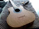
Got 90% of the inlay recess cut. The contraption I am using to route doesn't fit inside the curve of the lower horn so will have to do that part on the CNC.
|
|
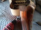
I had left a fairly generous neck heel originally while the body was being built and attached. Now I am in a pretty safe place to grind that down to a much smaller component of the instrument.
|
Left: While everything else is going on with the top, I am grinding away at the neck/body transition to minimize that area as much as possible and make the upper frets as easy to play as possible. Right: This is the mechanical setup for cutting the slot for the inlay around the body. I think it will work out fine just have to be very careful! |
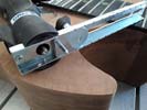
I'm going to be cutting a slot about 1/4"wide around the body fpr the green shell inlay. All being well I may also add an edge trim inlay. One step at a time!.
|
|
I need to prepare the top edge of the body so that can use that surface to guide the routing tools that will create the slots for the egd inlay.
|
Left: I am carefully filing and sanding all the way around the perimeter of the top of the instrument so that I have a smooth and reliable surface to guide the router that will be establishing the border treatment. Right: Testing all my dremel tooling so that I can get a nice clean machined surface around the edge of the top plate! |
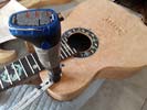
I will be using this dremel setup to prepare the grooves around the top plate for the inlay.
|
|
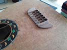
The new bridge looks really nice and all it needs is some sanding to get it ready.
|
Left: I have the new bridge being fitted to the location on the top plate of the bass. It will be pinned and glued in place so that it is really solid and can stand the tension of 6 bass strings! Right: I am fitting the bridge units to the bridge and also getting the bridge pre-drilled for support posts which will help bind it to the body! |
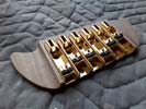
The bridge assembly is beautiful. I have six little slots to cut in the back for string end clearance and then I will fit it onto the body.
|
|
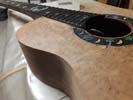
Befor I cut a channel for the shell I have to make sure the perimeter of the body is filed and sanded super-clean.
|
Left: Cleaning up around the perimeter of the body so that it is nice and clean. I will be using the body perimeter to define the perimeter recess for the shell inlay. Right: The bridge I recently created needs to be shaped to its finished profile so that I can permanently attach it to the top of the instrument. This bass will look pretty cool! |
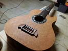
I have some minor machining and some sanding to do to the bridge before I get it attached to the body of the instrument.
|
|
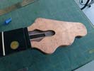
Great to have added this piece because now the top of the bass and the headstock match really nicely. After finishing these woods will look awesome.
|
Left: Faceplate on headstock has now been glued on and I trimmed the excess off to the perimeter of the headstock. May refine that outer geometry before finishing. Will engrave logo on truss rod cover. Right: I received my blue/green inlay shell. A little darker than I had envisioned but may still work out- will discuss w/customer. |
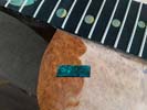
This blue green shell ended up ding a little darker than I thought it would be. Depends on the ambient light. Colors are great though. Expensive stuff but will discuss with customer in case I need to buy a lighter color.
|
|
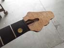
The headplate will look very nice when finished, plus we are planning to add a trim of the blue/green shell around the finished perimeter!.
|
Left: The faceplate for the headstock is the same material as thetop of the body so this will match very nicely. Still oversize but I will be trimming that to size and will get this attached on headstock. Right: Now gluing the headplate onto the headstock. Not an easy clamp because everything is on and angle and wants to move! |
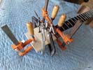
Gluing the headplate onto the headstock - another little step forward. Once this has set I will trim around the perimeter to clean everything up.
|
|
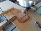
Doing a couple of machining operations here to harbest the truss rod cover out of the headstock faceplate.
|
Left: I had the faceplate for the headstock up on the CNC firstly to square the end off at the correct length, then I set up to cut the truss rod cover out of the material. Right: I'm using a very small carbide end mill to machine out the little plate that will provide access to the adjustment end of the truss rod. Will also be a nameplate. |
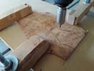
Cutting out the truss rod cover on the CNC.
|
|
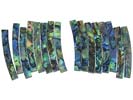
I will have to cut the shell to match all the curves in the top and headstock of the instrument but no dount it will look very impressive when done!!!.
|
Left: I'm ordering that nice looking shell from one of my suppliers and will plan on cutting and installing that as a strip slightly inboard of the outer edge of the instrument and the headstock! Right: I want to apply an inboard shell trim not unlike the one in the photo. Could do it a tiny bit wider and perhaps a tiny bit firther in from edges. |
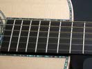
This is a rough idea of the shell trim I envision.
|
|
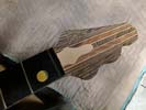
I wanted to make sure the truss rod access lid wasn't too big to get in the way of the tuners.
|
Left: Work is being done on the headstock plate to machine it to the correct fit and length and also to cut out truss rod cover piece from the plate material. Right: I did some shopping for the best color of shell that would work for the trim around both the body and the headstock. I have a suupplier in Hawaii that has a great selection! |

AI have several very nice choices in the blue shell options, These are all paua shell and they are all very nice. I personally prefer the upper left one.
|
|
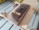
Just about to cut a few operations on a new bridge blank which will be ingerently a little stronger.
|
Left: Running a couple of programs to recut a slightly more rigid bridge unit than the original. Just want to make sure this part of the instrument is more than adequately strong for the tension of six bass strings. Right: Getting the machining done on the bridge. Quite a lot of little operations to make sure it comes out right!! |
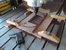
Being careful here to do all the necessary machining operstions in the correct order so that it all comes out the way I want it to!.
|
|
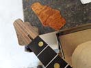
This is the same amboyna material that is on the top plate. I will harvest a truss rod cover from this piece before it is attached to the headstock. We have a plan to add some shell around the perimeter too.
|
Left: I am getting ready to cut this veneer for the headstock closer to size. I need to cut a square end on it and then machine a truss rod cover from the plate. Right: I decided to re-machine the bridge unit as some of the features on first one were too fragile. Have all the programs so I am just going to make a few modifications. |
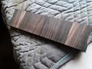
This wood - wheich I got from a fellow instrument builder, is a type of ebony. It has a very nice grain and is really dense. More on this soon!.
|
|
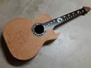
Great to getthe fingerboard attached and now part of the overall assembly of the instrument. I need to get the headstock veneer (which matches the body top) attached on theheadstock istelf.
|
Left: This is the instrument with its fingerboard attached and it looks pretty nice so far. I need to do quite a bit of cleanup work to remove excess glue squeezed out during the clamping process. Right: Lots of sanding and filing going on right now to finish up the work along the edges of the fingerboard. Looking nice already!! |
All that glue and the rubber band ends up creating a bit of a buidup along the edges of the neck.I'm currently filing and sanding that all back of so that I will end up with a nice clean neck and fingerboard.
|
|
The instrument is ready for the gluing exercise - I will be adding blocks under the neck to keep that area straight while under the tension of all the rubber bands.
|
Left: OK I have the instrument fixtured with a solid back plate and a section below the neck that permits the rubber bands to do their job. Just going to add a few blocks to support neck. Right: This was the very complicated gluing setup I went through to get the fingerboard attached. It helped a lot to have all the components on hand! |
This photo was taken not long after the gluing setup was completed. Lots of clamps and rubber bands involved.
|
|
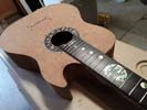
I'm not thinking of any good reason I shouldn't get the fingerboard attached to the neck - setting up for that.
|
Left: I'm thinking it's safe to go ahead and glue the fingerboard onto the instrument itself. I'm gathering materials to get that done. Right: OK I got all the tooling assembled for the fairly involved operation of gluing and clamping the fingerboard onto the bass. Once the fingerboard is on I will do a lot more carving! |
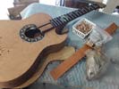
Gathering up all the required tooling and supplies for this task. So many uneven surfaces that the rubber band approach works best. Just have to have everything together before you start!.
|
|
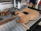
Most of the work on this operation is in the setup so that I guarantee alignment with the existing fingerboard surface.
|
Left: Setting the instrument up on CNC machine so that I can carefully machine the recently added support material flush with the existing neck angle. Right: The support material for the fingerboard has now been successfully milled down to match the neck-to-body angle. Not the easiest setup but everything went well. |
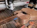
A tricky operation but it's now complete and I can move on!.
|
|
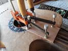
I want to get this section glued onto the body and then get it machined down to the same taper angle as the neck.
|
Left: I am now gluing the filler piece onto the top of the body. I have to be very careful about alignment to the existing neck edges. Right: Gluing setup completed - a little more complicated than I had planned as I needed more clamping pressure around the plate to guarantee the joint quality I wanted in this area. |
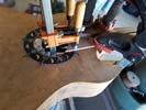
Gluing under way - next will probably be machining on the cnc.
|
|
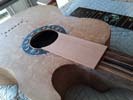
The job of this filler piece is to provide support under the fingerbard between the end of the neck and the soundhole. Because there is a necessary neck-to-body angle this area would otherwise be a very small gap. After gluing, the wood will be machined down a very thin tapered section.
|
Left: I shaped and sanded this piece of material for support under the fingerboard between body end and soundhole and I am now going to attach it to the instrument. Right: Another part of the fingerboard fitting process was to cut out the back of the fingerboard to match the radius of the sound hole. This has now been successfully done. |
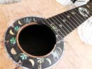
In order to get the fingerboard attached I needed to cut out material from the back end to match the curve of the sound hole. This has now been done clearing the way to getting the fingerboard attached to the neck of the instrument.
|
|
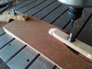
This piece of material will be glued to the top of the instrument body and machined flush with the surface of the neck/fingerboard joint surface.
|
Left: In this photo I am cutting a piece of matching material which I will attach to the top of the body as a support plate to the end of the fingerboard. Right: I am setting the instrument up on the CNC so that I can machine the support area under the fingerboard so that it is in line with the neck-to-body angle. |
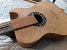
TOnce I machine this piece down parallel to the top surface of the neck I will be able to attach the fingerboard!
|
|
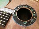
I will be removing some of the fingerboard material to create a radius to match the soundhole.
|
Left: Two things I need to do now - one is to carve the radius of the soundhole out of the fingerboard and then I need to add some support packing under the fingerboard so that fingerboard will fit solidly onto top. Right: I marked the end of the fingerboard to establish the area that needs to be blended with the soundhole and cut out. |
This area I marked will be removed so that the end of the fingerboard blends with the soundhole. Also working on the support material under the fingerboard between the body edge and soundhole.
|
|
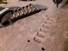
Part way through the machining for the bridge and all seems to be going well.
|
Left: I am just finishing up the first machining operation where I am creating clearance for the bottoms of the Hipshot bridge units. Then I will be drilling some holes. Right: Recesses machined and holes drilled and the bridge fits very solidly on the top of the instrument. I have some machining and inlay to do to the bridge. |
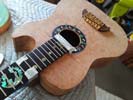
Got all the machned features for the bridge done and the body is off the machine. I have some work to do separately on the bridge although I think the next major task will be to attach the fingerboard onto the neck!.
|
|
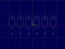
Working on the programming of the machining for the bridge attachment.
|
Left: This is the pattern I will be machining on the CNC for the bridge assembly. It will create recesses for the hardware and holes for screws and piezo wiring. Right: The instrument is now set up on the CNC and I am ready to do the machining for the bridge. Once this is done I probably need to look at attaching the fingerboard! |
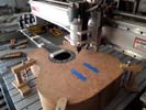
Due to the thickness of the body this ended up being a pretty fancy setup but I think I have everything set up for a successful operation!.
|
|
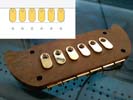
I will be doing some machining on the top of the instrument body to create recesses for locating the Hiphot saddle assemblies.
|
Left: I drew out in my vector program the recesses and holes I need to establish on the top of the instrument body. This will allw the bridge to sit solidly on the top and provide retaining screw holes. Right: I am setting things up on the CNC so that I can cut recesses in the top plate to allow the bridge to fit firmly on the surface. |
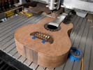
I will be machining six recesses and 12 holes for screws/wires etc.
|
|
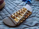
I will be finishing the machining on the two outside ends of the bridge plate and getting that down to a nice surface finish. Then I need to consider some possible inlay options based on the theme of the rest of the instrument.
|
Left: Fitting the Hipshot bridge units into the machined slots in the bridge (some of them were a little tight). I need to do some machining on top plate to allow the assembly to fit in place. Right: Working on the bridge placement so that I know what holes I need to drill for piezo wiring and grounding from the metal components to common ground. |
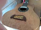
Bridge fits fine with the 4 positioning pegs but I have to machine out some material to clear the bottoms of the bridge units and create wiring channels (piezo and ground).
|
|

The bass will have 4 tuners on the bass side of the headstock and two on the treble side. These are pretty lightweight units.
|
Left: I now have the custom set of Kalium strings in stock and ready for installation on this bass. I am looking forward to hearing how the chamber on this bass responds. Right: The gold tuners came in from Hipshot and I'll be able to check out their installation positioning and move the headstock area forward to the neck few stages. |
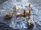
Great quality hardware from Hipshot. These will look really nice on the bass.
|
|
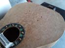
Top of the instrument has been drilled for the attachment of the bridge.
|
Left: I have now established the four positioning holes for the bridge into the top plate assembly. I have a little work to do on the bridge itself before it goes on but once it's ready it can be attached. Right: I decided it's time to order the tuners for this bass which I always buy from Hipshot in NY. Great quality products tried and tested! |
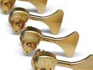
The bass will have 4 tuners on the bass side of the headstock and two on the treble side. These are pretty lightweight units.
|
|
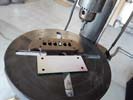
The drilling template did a good job of allowing me to drill the 4-hole pattern centered to the bottom of the bridge. Now I have to repeat those holes in the top of the bass.
|
Left: I used the template to drill location holes in the back of the bridge. That went very well. Now I have to carefully position the template on the body to drill the same hole pattern. Right: OK, I got the bridge hole template very carefully placed based on scale length and centerline of the neck and fingerboard. Time to drill the holes! |
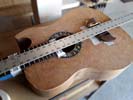
I'm ready to drill the 4 pin holes that will place and secure the bridge to the top plate of the instrument.
|
|
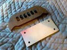
This very accurate plate will allow me to drill 4 holes in the bridge and in the instrument top to securely attach the bridge unit.
|
Left: This is a small drilling fixture I cut on the laser which will allow me to establish four 1/4 inch pins to locate and provide strength to the bridge-to-body joint. I will post more pics as I move through this. Right: Today I ordered the custom set of bass strings for this bass from Kalium to the specific diameters listed above.
|

Got the custom set of string diameters ordered from Kalium.
|
|
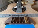
Getting things ready to attach the bridge.
|
Left: I'm marking out locations for pins to set the bridge positioning. I'll glue those into the bridge and then will be gluing the bridge onto the body. Also will be drilling holes for the output bridge wiring. Right: I'm starting some of the preparation work on the back place of the body so that I can get it ready to attach when the body is ready!
|
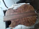
I will be doing some work around the edges of the back plate to get it ready for assembly onth the back of the body where I recently did all that machining.
|
|
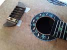
Placement of the bridge and fingerboard helps me plan the relief at the end of the fingerboard and the mechanic of connecting the bridge to the body.
|
Left: I did some careful measuring to make sure the placement of the bridge will be correct based on the scale length of the instrument. Also checking height with the bridge units. Right: First inportant result is the area I need to remove from the back of the fingerboard to match the soundhole. This looks just about right which is good! |
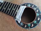
I'm planning to get this fingerboard added on soon but because of its relationship with the bridge some of these things have to be caculated and planned together. The pencil line approximates the radiused area that I will remove to match soundhole.
|
|
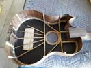
Feels very good to get all this tricky CF work done. I have a few small areas which need to be ground back but overall a very solid end result!
|
Left: I have a little cleanup to do but have succeeded in getting all the carbon fiber securely attached to the inside of the top plate. I will clean up with a grinding tool and post a glamour shot! Right: Spent some time grinding out some small areas to clean up the edgs. I can now look at getting the bridge set onto the body!!! |
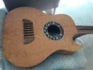
I'm going to make sure I have accurate positioning for both the fingerboard and the bridge and then work on getting the bridge finished up and permanently fixed to the instrument.
|
|
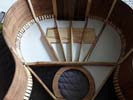
Once the CF is applied I will be cutting and installing for the beidge components!
|
Left: All my little templates are doneand fitted and I'm cutting the CF material right now. Will get more epoxy mixed and get all these pieces on! Right: More carbon fiber pieces being installed in the body. These smaller pieces are a little more work but it will be worth it when the job is complete and I can move forward! |
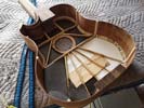
Some glued and un-glued fiber in here. The big pieces are fairly easy - the smaller ones are a lot of work!
|
|
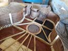
Two more sections being glued - it's a little tricky and needs some care and patience!
|
Left: Working my way around the underside of the top plate. Got two more sections glued up and will keep things moving until they are all sealed and solid. Right: I cut more carbon fiber pieces and I'm busy gluing those into the areas of the top plate to complete the CF bonding with the top plate. We'll have a complete body soon! |
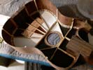
Working my way through the instrument and will be done with the carbon fiber very soon.
|
|
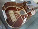
This is a pretty critical operation. I mixesd up some of the SAME adhesive I will use for the CF material but added a little extra setting compound to slightly speed up the curing time. I added this sparingly to the inside surfaces of the Amboyna in the hope that this will seal quickly and provide a protective layer that will prevent the next application of adhesive from seeping through!!! I have never done this before so I am being super-cautious!!!.
|
Left: In preparation for adding carbon fiber I needed to seal the somewhat porus top material so that the adhesive I use with the CF does not soak through to the front of the instrument!!! Right: Starting this process cautiously with two areas. I applied aerospace grade epoxy to the bottom surface, added CF material then soaked with more epoxy. |
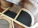
These two aareas should prove out the orocess. I wetted the bottom area - placed the CF material onto that, then soaked the CF through with more epoxy. No reason why this should not work!
|
|
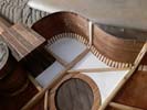
I'll cut the carbon fiber just a tiny bit larger than these paper templates and that should work fine. As with everything else it will have to be done with great care!.
|
Left: I'm setting up templates for the individual areas that will be getting the carbon fiber treatment. I will number these and get the material cut accordingly. So far so good. Right: This is my first piece of carbon graphite sheet on the back of the top plate. I'm giving the underside of the top plate a light coat of epoxy to seal it first. |
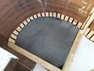
After I apply a light sealer coat of aerospace grade epoxy to the bare wood under the top plate I can confidently add the carbon graphite material.
|
|
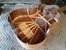
Machining of the lower edge of the sides was quite a lot of work as I had to do it all in small cuts that the thing material would tolerate. I now have a nice clean edge all the way around.
|
Left: This is the body after the machining of the lower edge of the sides. I now have a nice tapered surface that will accept the back plate whe it is ready to go on. Right: I have the carbon fiber material here and ready to cut to reinforce the areas under the top plate. I'm doing a test on a small piece of Amboyna first for safety. |
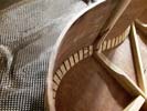
I'd love to cut the carbon fiber cloth on the laser but it doesn't respond well to that - I will devise an accurate way to cut it and we'll get this added to the instrument.
|
|
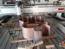
This setup will allow me to machine the sides to an even tapered plane from frot to back.
|
Left: Now it's time to cut the lower edge of the sides to one complete plane so that the back can fit on there. The body thickness will have a slight taper from back to front. Right: I've done quite a bit of machining already to rough down the sides closer to their finished dimensions. I have to go slow as the sides wont tolerate a big depth of cut. |
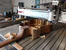
I have roughed the sides down to very close to final dimensions. A few more cuts to clean up and we'll be done with this operation.
|
|
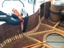
Each one has to be glued with pressure applied in all three axes in order to guarantee a good joint.
|
Left: Inside view of gluing vertical side supports into the body cavity. Once I have all six secured I will machine the bottom edge of the body on the CNC - Should be interesting. Right: Gluing the last of the six vertical side supports into the structure of the instrument body. The whole thing feels really strong and solid now! |
Just about done with the structure of the insude of the bass body.
|
|
Installing four vertical braces to support the side panels.
|
Left: I am now installing the right angled side bracing inside the body. They are only four of them but they need to be individually carved to fit their respective locations on the curve of the body. Right: I actually have 6 of these side supports which are all carved and shaped to fit - I am now gluing them in place around the inside of the body. |
First of the six side supports being attached.Also gluing at fillet in behind the side/neck joint.
|
|
I need the top and the sides to be fairly well blended because I'm going to be routing around the edges to create a little channel for the binding.
|
Left: Just finished blending the top edges around the perimeter of the top. I am now installing vertical side support pieces from the ends of the top bracing to maintain squareness and rigidity. Right: When these angled support pieces are all in I can machine the back edges of the side pieces to their final body with measurements. |
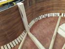
I'm adding four side supports to maintain the integrity of the sides. I'll taper them slightly and get these installed.
|
|
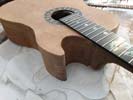
Looking quite good around the lower horn after some sanding and shaping.
|
Left: I did a lot of sanding around the undercut on the lower bout. Now I need to set this whole body up on the CNC so that I can cut the sides to a tapered thickness between the neck and the back end. Right: Working on a setup on the CNC where I can machine the sides to an even tapered plane ready for the back plate. |
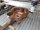
I'm tooling up for a fairly difficult clamping situation to stabilize the body at a slight angle so that I can accurately machine the sides.
|
|
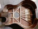
Very nice to have all these pieces glued into one! I am now working on how I will cut the back sirface of the sides and also will probably attach the bridge and do anything else that requires work on the inside of the instrument.
|
Left: Sides are now officially bonded to the top plate and the instrument feels good and solid. One of my next tasks is to machine the top edge at a slight taper between the front and the back. Right: Now I am busy filing the joint area between the lower side and the hand recess so that we have a nice smooth joint transition. |
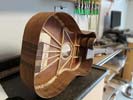
I left extra material on the end of the lower horn just in case, now I am prmoving it to blend with the lower sidepiece.
|
|
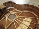
Good to get the whole edge of the top done - I am now moving to the lower half to complet that.
|
Left: Just about done now with the upper side of the body and I am moving on to finishing the lower side. I only have to put in a couple of custom supports near the bracing areas. Right: This gluing setup is a citical one as I am bonding the lower side to the top and at the same time creating the joint betweeb the side and undercut. |
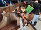
Wish meluck on this one - it was a clamping nightmare.
|
|
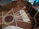
Second part of the upper half of the body. Will be adding more blocks to the joint area.
|
Left: Gluing the second section of the upper side. I'll be adding more stabilizing blocks as I move forward - so far everything seems to be working well. Right: I glued the top half of the side into the recess in the neck and I am now securing the front half of the upper side to the top plate. I'll be adding more support blocks too. |
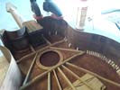
Attaching the last section of the upper body half to the top plate.
|
|
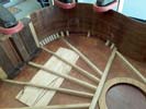
Assembly process continues using angled blocks I made for support. I will be adding more of these before gluing the next segnent
|
Left: Now gluing up to the next piece of bracing and also have glued in block supports which are necessary for holding it all together and for housing the binding on the outside. Right: Started gluing on the other side of the body to work that side forward to the front joint. I will be adding support blocks along the way. |
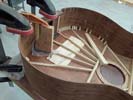
Working now on the top body half. As soon as glue dries I will do more.
|
|
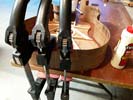
Started the process of attaching the sides to the top and neck.
|
Left: Right now I have the very back section glued and clamped together. When the glue is set I will be able to progressively glue the sides areound to the two joints at the front of the body. Right: Now gluing the next section on the lower body side and when that sets I'll keep moving forward until I can glue that joint in the front. |
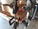
I am gluing the next few inches onto the top plate. Before I unclamp I am planning to add a set wood bracing pieces to the inner joint for strength and support.
|
|
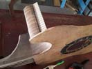
Added a little surface support for the joint area where the side meets the inner curve assembly.
|
Left: My next job is a big one. I will have to glue the sides to the top/neck assembly in one big operation. Bottom looks good - adding support and trim to the forward end of the top side just a little first! Right: I tried gluing from the front joint backwards but it was very hard to keep lateral pressure on the joint. Decided back to front was better. |
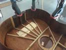
Decided to glue the back end first and work forwards. Working the opposite way did not give me enough clamping options.
|
|
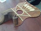
Always a little nervous when unclamping a complicated assembly piece like this.
|
Left: I unclamped wverything to take a look and see how everything went together. Looks good even in this rough state before sanding. Also need to trim down the height of the curved piece. Right: With the first component in place I am now able to test the fit between that part and the back of the body so I can attach the lower side. |
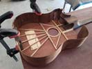
Testing the interaction of the sides and this newly glued part.
|
|
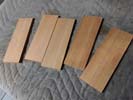
EI will shape and cut this material into individual pieces which I can use to support the top and side joints.
|
Left: I cut and sanded some material which I will use as internal support pieces for gluing the sides onto the top plate. The resulting pieces will create a very strong joint between top and sides. Right: I am now gluing the curved assembly onto the existing instrument assembly. I'm then hoping that I can create a good joint with the sides!! |
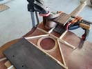
I'm gluing the curved undercut assembly onto the instrument. If all goes well I will be able to fit the end of the side material cleanly into this piece!.
|
|
I am being extremely careful and calculation as best as I possibly can all the angles to make this critical joint come out right..
|
Left: I am machining a joint face for the area where the lower side meets the undercut assembly. Not an easy operation as there are so many inter-dependent angles to consider. Right: This is the result of the recent milling operation where I have a pretty good joint between the teo pieces. I'll go ahead and attach the assembly to the top. |
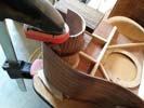
Ended up being quite plaeased with the resulting joint. I think these can now be glued together!.
|
|
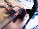
Trying to straighten out a small piece of the side material before I glue this piece on.
|
Left: before I attach the radiused undercut piece to the instrument I'm just clamping it in a wet condition to move the inner wall a tiny bit. If it's close enough when I unclamp I will go ahead and glue it on! Right: Now I am cutting a little recess in the curved assembly into which the end of the lower side piece will fit. Can't wait to get sides on!
|
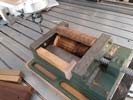
The positioning and angle of this little step is very important so I am being super careful.
|
|
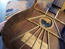
Testing the lower side and I have marked out where I want to modify the bends for the best fit.
|
Left: On the lower (left) side I am very close. I trimmed the bracing and tested the side in place and there are only 2 places I need to make minor bend modifications. Right: I'm fitting the inner curve to the body and the end of the side material to the inner curve. Not easy to do but once it's done the sides are complete and can be attached! |
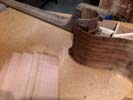
Not an easy job to make these parts join together the way I want them to but they will and I am almost there.
|
|
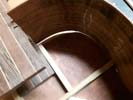
Everything almost fits just the way I wanted it - I need to apply a little heat to the upper curve and we'll have this done!.
|
Left: I trimmed the length of the top half of the body side a little shorter. Almost fits I just have to bend the upper curve about another 10%!!!! So close! Right: The bending on the upper side is done and the while top half fite great. I have one bend on the lower half to do for the same purposes and we can get the sides attached! |
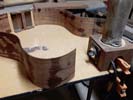
Bending requires the application of a lot of water on the bend area. The heated post on the right evaporates that water in the wood and helps the wood grain expand and contract to permit a little movement.
|
|
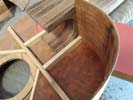
Some careful side fitting at the area where the side meets the top side of the neck.
|
Left: I'm now removing material and the neck end of the side pieces so that I can do a complete fit of the upper side. Have to do it carefully as taking too much of would create leave the side too short. Right: Happy with the top section - everything fits with the exception of of a slight heat bend that I need to get the very end to fit. |
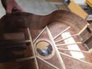
This is quite a tricky job but almost done! Once I get this done on both sides I can join the top and sides together!.
|
|
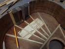
The objective for doing this work is to get a solid fit between the top plate and the sides so that they can be glued together and then reinforced.
|
Left: I have trimmed the readr three braces to get the back support set in the right place. This in turn allows me to mark the specific places to trim to the mid and front braces. Right: Working forward from the back I am cutting and bending material to achieve the desired fit top to bottom to prepare for assembly!! |
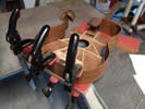
I'm clamping the areas that are already good and heat bending and cutting the forward areas so that I will end up with a nice stress-free fit between top, bottom amd sides.
|
|
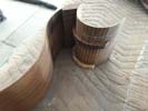
Gluing the first of two supportt pieces onto the relief curve.
|
Left: This little sub-assembly is now complete except for nbeing cut to final body height, and I'm going to now find a way to get it connected to the rest of the body so that it all makes one piece. Right: I'm now trimming the bracing under the top so that I can get the sides to fit all the way round from the back to the neck area. |
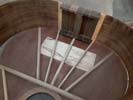
Starting at the back I am marking and trimming all the ends of the bracing pieces so that I can work on fitting the sides.
|
|
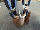
This is my next assembly for the lower body half.
|
Left: The support pieces are now getting glued onto the curved piece one at a time. Once they are both on this should create a very rigid and stable assembly! Right: The first brace was easy compared to the second one but I got it clamed on and the glue is setting - should work out just fine. Will post a picture of the end result. |
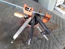
I now have the second support piece glued and clamped.
|
|
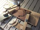
I calculated the curves that would match the inner radius of the cutout and cut these shapes on teh CNC. I cut each pair at opposing grain directions and I will glue them together to create the strongest but lightest radial supports.
|
Left: Cutting two sets of little wooden support braces to help keep the undercut curve from being internally stressed. I'll glue these to the inner side of the curved piece. Right: Gluing those little support pieces together and as soon as they are done I'll clean them up and get them assembled with the curved side piece! |
Gluing together my custom support pieces. Glad to have a CNC where I can fabricate special pieces like this.
|
|
Doing some top and back alignment in preparation of upcoming work.
|
Left: I'm laying the top and back on top of each other so that I can make sure curves around the lower horn are matching. All related to getting the little curved assembly to fit. Right: Checking the curved assembly piece as I may fabricate a couple of braces to support this fairly tight curve. Makes for a more rigid and slid assembly. |
Temporary test assembly so that I can mark out curves and design a couple of support braces.
|
|
This Little assembly will become the portion of the side of the instrument below the neck.
|
Left: This is my little sub-assembly which I will be gluing together as part of the sides of the instrument. I will do some machining on the area that joins the lower side also. Right: These parts were pretty difficult to clamp and glue together due to their shapes. I found a part of my bandsaw that has just the right kind of support. |
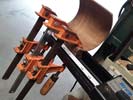
I'm gluing the inner curve side piece to the little end block.
|
|
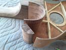
In order to join the side pieces together I have to do some machining to the block that creates the sharp end of the undercut.
|
Left: I'm getting all the side components together to try to get the best fit all around the body. I'm anxious to get the body parts assembled into one piece! I have to machine the block on the lower left.. Right: According to my measurements this line is where I should trim this piece to. I'm going to cut it a re-test the fit. |
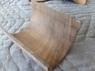
This part has to join together to create a side assembly that fits the top plate so measurements and resultic cuts are quite critical.
|
|
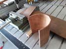
Working on getting the right curve and the right length so that this piece fits in place.
|
Left: The only way I could think of to cleanly cut the extra material off this piece was to use the CNC and a very small carbide end mill. Worked out quite well with a nice clean cut both ends. Right: Text and picture coming. Right: In order to get the curved side piece to fit I had to remove some internal material on the inside of the body.
|
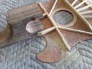
Some manual carving work required to get the curved side piece to fit in place.
|
|
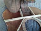
A little tricky but I'm getting these part to all fit together.
|
Left: I got the tight bend of the side wood insert to fit the curve for hand relief. I'll need to go ahead and cut the curved piece to the right length and body thickness so that it can be fitted. Right: I'm ready to cut this piece of wood I have so carefully bent. I need to trim it to fit and install it exactly in place under the neck. |
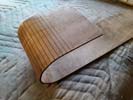
I'm going to trim both ends of this piece. It will be installed in pace as the fist component of the sides.
|
|
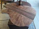
Using the spindle sander to do some modifications to the back plate perimeter.
|
Left: I marked the top and bottom plates and used the spindle sander to grind my way up to the line where I had marked the target perimeter. Right: In this photo I am using the spindle sander to cut and shape the curve for the hand clearance. This gets me closer to being able to assemble a complete body for this bass. |
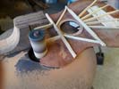
Spindle sander also worked very well for removing material in the top plate to create the clearance on the lower bout.
|
|
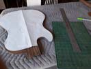
Bringing top and back together using the common reference. This will allow me to do some fine tuning also on the sides of the body.
|
Left: The template allows me to plan for some material removal around the back plate. This will ensure that top and front are matching profiles. I will also be doing some final bending of sides! Right: While working on the body profiles I also did some carving work all over the neck profile and around the headstock area |

Getting top plate ready - will be removing a little material.
|
|
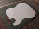
This template gives me a filal body shape.
|
Left: I now have a body template that defines the perimeter of both the top and the bottom plates of the body. I'll use this to bring the two shape geometries close together. Right: Not a great pic, was taken at night - but I'm about to trim the edges and remove the hand relief from the lower body half. Body assembly coming! |
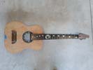
Getting top plate ready - will be removing a little material.
|
|
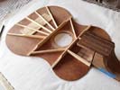
I'm cutting a revised template for the body outline that allows for any differences in the top and back plates.
|
Left: Now working on the top and bottom plates of the instrument using the template to bring the two profiles close together. I want to get the sides set up for assembly. Right: I did some careful sanding to top and bottom boards. Also refined some bracing where I was able to make it a little thinner without compromising strength. |

This is a really tight bend for any piece of wood but looks like we are good!.
|
|
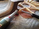
Carving the clearance for the lower body side piece as it meets the neck.
|
Left: I am working on the joint area where the curved hand area at the bottom of the body will meet the neck. This will allow me to fit the curved piece into the recess of the side of the neck. Right: Did what I believe to be the necessary bending on the hand relief curved piece and I can now finish up the fit against the neck/body assembly. |
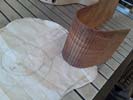
This is a really tight bend for any piece of wood but looks like we are good!.
|
|
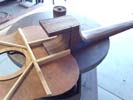
My goal is to get the top and bottom plates to match fairly closely so that I can use the sides to bring all the pieces together!.
|
Left: working on the lower half fo the neck/body joint area so that I can test fit the concave side panel. I may have to re-bend very slightly but that should be no problem. Right: Bending the lower bout neck relief piece so that it meets the curve of the template. Should bend pretty well as I lasered the little slots in the inside surface! |
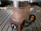
Some adjustments to the curve of the hand relief side curve.
|
|
Making sure the top plate and the back plate are consistent with each other. I will be marking both and working on the lower body cut area.
|
Left: I am using my body template to establish and mark out the body perimeter both on the top plate and on the back plate. I need to cut the area of relief next to the neck. Right: My goal here is to make sure the top and bottom plates are pretty much the same shape and size. I need to cut the lower bout neck relief in both. |
I will be adjusting the profiles of top and bottom plates to get them to match each other pretty closely in final shape.
|
|
Last of the bracing being attached to the top plate.
|
Left: Last of the top bracing pieces being glued onto the top-neck assembly. Feels nice and solid already. Once this is done I can do some fitting for the bridge hardware and refine body shape. Right: I'm now looking at the upcoming fit between the neck and top assembly and the sides of the body. May need to heat bend a little to fine tune shape. |
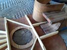
Starting by testing and fotting the lowe bout inner curve for the neck relief. I'll set the fit to the body and then refine the bent curve to accurately match the top plate.
|
|
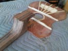
Top and neck are one piece now - next I have to add some final bracing.
|
Left: We now have a top and neck assembly. I need to add the final bracing components so that I create a fairly rigid top plate assembly. The sides will also add a great deal of structural strength. Right: I am now gluing on the additional bracing pieces to complete the structure under the top plate. Should end up nice and solid. |
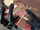
TI am gluing 4 additional bracing pieces to the top.
|
|
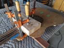
In this photo I am gluing and clamping the top plate onto its machined surface on the end of the neck blank.
|
Left: Everything carefully marked and measured and I am now gluing the top plate onto the neck of the instrument. Before gluing I cleaned up a few internal neck heel surfaces. Right: Made two more braces to support the area between the two big lateral braces. They are only small ones but will help keep everything stable. |
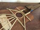
The small additional bracing pieceshelp keep a straight center support front top back.
|
|
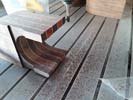
ThThis would be harder to do once the nack and top are connected so worth doing before assembly.
|
Left: Quick operation on the cnc to clean and square up the back edge of the neck unit. This will be inside the body but wanted it nice and clean and square top and bottom. Right: I now have a nice clean set of machined surfaces on the end of the neck to which other pieces can be attached. I'll go ahead and glue the top plate on next. |
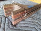
Surfaces and guide marks ready for the attachment of top plate to neck.
|
|
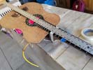
The bridge needs to be set accurately based on scale length so marking this out lets me set up for some machining required on the top plate .
|
Left: I am marking the exact location of the top, neck and fingerboard so that I can set things up to do a little machining to get the bridge placed and installed. Right: Setting up to glue the top plate onto the heel section of the neck. That will establish some solid positions for many of the other features on the instrument! |

The bridge needs to be set accurately based on scale length so marking this out lets me set up for some machining required on the top plate .
|
|
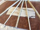
I will also be thinning down the outer ends of the three larger braces - most of the strength we are looking for is centered under and around the bridge.
|
Left: Got all but two of the braces glued onto the top plate assembly. The last two I decided to slim down a bit to reduce their mass and thin them down more toward the outer edges. Right: The top is out of the vacuum press this time having the last two middke braces attached. the back section should now be strong enough for the job! |
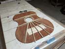
All the bracing on the top plate has been done and I will now lok at the fitting of the top, fingerboard and neck so that I can correctly place the bridge attachment.
|
|
TVenter brace and base plate being glued together.
|
Left: In this photo I am gluing the center brace to the baseplate since doing this will help me place the final assembly more easily. Right: I now have the top and the little sub assembly in the vacuum press to apply the right amount of compression while the adhesive sets. Once this is done I'll clean off any excess glue. |
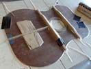
Gluing baseplate and center brace in the vacuum press.
|
|
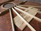
Almost done with the creation and shaping of these braces and I will be attaching the whole assembly to the back of the top.
|
Left: Braces are now smaller and rounded off on the tops. I will taper the ends towards the outer edges and once that's done I'll start attaching everything to the back of the top plate. Right: All five of the back braces are being tapered off at the outer areas. I don't need the degree of supprt at the edges of the top , mainly under the bridge. |
This is one of the braces after I tapered its thickness off towards the outer end.
|
|
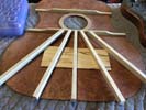
Components for the bridge and top plate support have all been cut. Now I have to carefully shape them and make them all fit perfectly.
|
Left: The braces are rough cut and I also cut a support plate to go under the bridge and sanded it to the required thickness. I will now shape all these pieces before assembly. Right: I cut the back spport plate at 15 degrees either side so that I could locate the outer two braces. Now I have to cut recesses in the two center ones. |
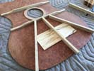
Starting to take shape here - two more to fit and then I refine their shape to be a little smaller and I can get this all attached.
|
|
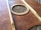
These two braces are very solidly attached, I have four more plus a small support plate to add under the bridge.
|
Left: Both initial supports are now solidly attached to the top plate of the instrument. I am cutting a set of rear braces which will be added to the back under the bridge area. Right: This will probably be my best solution for rear bracing to give the bridge area a good amount of support and stability. Lot of tension on the bridge! |
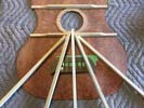
With six bass strings pulling hard on the bridge I want the top to be well supported and pretty rigid.
|
|
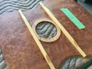
Ready to glue on the two transverse braces.
|
Left: There are the next two pieces that I will attach. I machined the sides of the inner disc to bring the two braces a little closer together. It also guarantees that they will go on square. Right: I'm now gluing the two transverse supports onto the back of the top plate. I'm doing them separately as it's easier to fully clamp them. |
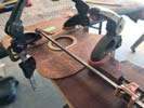
Once I have there two braces attached to the back of the top plate I will add ab array that will e designed to support the tension and pressure on the bridge.
|
|
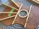
After some careful consideration this is the way the top braces will be distributed.
|
Left: Because we don't have to acccommodate string pins through the bridge it is a little easier to plan for the structural assembly below the bridge. Just want it to be strong and stable! Right: The support ring under the soundhole has now been attached and sanded and sealed. I will now be able to attach some of the bracing. |
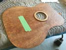
Got the support around soundhole done and now I am preparing to add some lateral bracing.
|
|
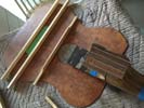
Text coming.
|
Left: I have bracing marked out based on the footprint of the bridge assembly so that allows me to move ahead and get some of this bracing attached. Right: I also cut some additional bracing pieces as I will be placing these under the top for maximum rigidity and need to have a few options on placement just in case. |
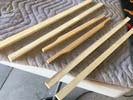
I am going to use these pieces to create custom bracing for the top plate.
|
|
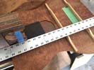
Accurately plotting the bridge location allows me to plan for adding bracing under the top plate.
|
Left: The bridge location and the geometry of the bridge hardware have been set and I am now creating locations and carved material for the bracing of the top plate. Right: This is some of the bracing I have been creating so that I can build up a supportive network of bracing under the top plate of the instrument. Should be interesting! |
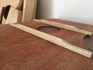
I cut some of the initial bracing pieces - there will be a few more to create the support matrix.
|
|
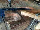
Machining a step on the lower half of the neck for the side joint.
|
Left: The lower side of the neck has been machined to create a step which will allow the curve of the lower side to fit. I will finish the area by hand when the lower bout is connected. Right: I am using the geometry of the bridge assembly to define the position of the bridge on the top plate based on the top/neck sub-assembly. |
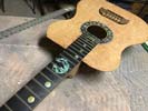
Accurately plotting the bridge location allows me to plan for adding bracing under the top plate.
|
|
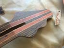
Once the fingerboard goes on the neck I will be attaching the Amboyna headplate.
|
Left: I scraped and sanded the top face of the headstock to remove machining marks and to create a nice smooth and flat surface for the headplate. Right: The slot for the side material meeting the neck section has been machined. I now have to machine a corresponding area on the other side of the neck for the curved plate. |
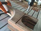
This slot will allow the accurate placement of the upper body half and its connection to the neck of the guitar.
|
|

With these parts fitted I can now look at the joint areas where the sides of the instrument meet the neck.
|
Left: Cutting a little piece of material to match the existing woods to allow the fingerboard to rest on solid wood between the joint and the soundhole. Just an aesthetic cnsideration but should be done now. Right: I'm checking the to-to-sides fit before attaching sides to neck to make sure the components align correctly. |
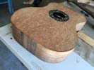
It's valuable to keep checking the alignment - I may do some minor re-bending to make all the curves fit without any bending stress.
|
|
The slot that I cut in the side of the neck has top be very accurately positioned.
|
Left: Setting things up on CNC so that I can machine a slot that will accept the upper edge of the body side. I have to be a little careful about angle and location but it should work out fine. Right: Working with the sides of the bass to make sure the ends are going to meet at the right places. May have to trim a tiny bit off on length.. |
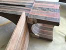
Checking slot locationand how much to trim off the end of the side material.
|
|
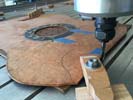
This little flat will allow the neck and the top plate to be joined together at the correct angle.
|
Left: Machining to clean up the front edge of the top plate so that I will have a nice joint onto the neck blank. Will be marking it up to assure good placement on the neck centerline. Right: The top and neck now fit nicely together at the correct neck-to-body angle. Now going to do somework on the sides of the neck where body joins. |
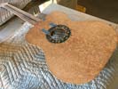
With these parts fitted I can now look at the joint areas where the sides of the instrument meet the neck.
|
|
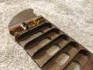
Less bridge height I create in this assembly the less neck to body angle I need. I think this helps arrive at a very good compromise.
|
Left: Based on neck angle and to keep that within normal limits I machined a little more depth out of the bridge recesses to lower the overall bridge height. Right: I cut the recess on the end of the neck upon which the top plate will be fitted. It is cut at a slight angle to the top to account for the height of the bridge assembly. |
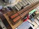
This little flat will allow the neck and the top plate to be joined together at the correct angle.
|
|
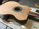
Done most of the necessary calculations to make these pieces combine correctly together. I'm getting ready to cut the recess in the neck for the top which defines the neck-to-body angle and several other things.
|
Left: The next cut I will be making will allow the top plate to nest into the top of the neck section. This involves also knowing where sides join the neck! Right: I decided to have the upper body side join the neck at the 15th fret dot - this location creates the best balance between fingerboard, neck joint and soundhole |
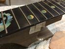
I measured all the components carefully and decided that this formula placed the end of the fingerboard at the best location for the soundhole and its artwork.
|
|
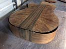
THis drawing (from Illustrator and inported into my CAM software) will allow me to get the bulk of the work done to the bridge. There will be more shaping and probably inlay but those will be seaparate operations.
|
Left: I'm trimming the braces on the back plate of the instrument so that they match the profile of the top and the template. I need to make sure they are all close to the same size. Right: Getting ready to attach the fingerboard to the neck which will in turn allow me to assemble other pieces of this instrument. |
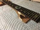
THis drawing (from Illustrator and inported into my CAM software) will allow me to get the bulk of the work done to the bridge. There will be more shaping and probably inlay but those will be seaparate operations.
|
|
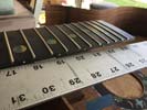
The neck and body relationship is one of the most important features on an instrument like this.
|
Left: Just making sure the area of the fingerboard over the top plate has about .070 of compensation for the bridge. That tells me where I cut into the heel of the neck. Right:I'm now setting up clamping and fixturing to get fingerboard and top plate together. This will in turn help me with connecting front ends of sides to neck heel. |

THis drawing (from Illustrator and inported into my CAM software) will allow me to get the bulk of the work done to the bridge. There will be more shaping and probably inlay but those will be seaparate operations.
|
|
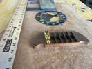
Getting the correct angle is a combination of calculating everything on the computer to achieve one set of results, then doing a detailed physical check to verify that things work they way you expect them to. I now have a reliable neck to body angle.
|
Left: Working on getting just the right neck angle based on bridge assembly height and fingerboard height. It will be just over one degree by the looks of it. Right: Machining down some of the areas on the bridge to bring it to a more finished overall apprarance. Sanding next. Will be using the laser to create matching inlay. |
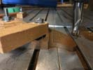
I'm machining down the outer ends of the bridge piece to blend it with teh rest of the body. It also creates a couple of areas on the bridge on which we could add inlay features..
|
|
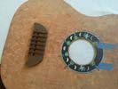
Just wanted to see what bridge looked like on the top plate.
|
Left: This is approximately where the bridge will be located - it wil be defined by the final position of the fingerboard but I think it looks pretty nice. Right: One of my next goals is to get the neck attached to the top plate based on the net height of the bridge saddles and the scale length which established the bridge location. |
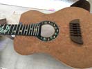
I'm establishing neck position based on bridge position as they all inter-relate on the 33 inch scale length.
|
|
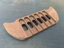
Wood looks light colored when dry but when it is finished it have a beautiful complimentary color and figure to the top.
|
Left: I went ahead and cut the bridge out of its parent material so that I can continue the shaping of the bridge itself. Right: Our bridge with one of the gold bridge units test-fitted. I will be doing some shaping of the wood areas of the bridge plus I have some interesting thoughts on inlay! |
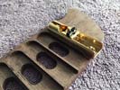
Yest fitting the Hipshot hardware into the bridge slots. I made them nice and snug for the most solid assembly possible.
|
|
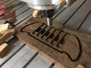
Did quite a lot of machining to get the bridge into this condition but it looks like this will be a great little assembly.
|
Left: I have now machined the recesses for the hipshot hardware and ran another program to create recesses for the locating/wire blocks. Should be a really nice bridge. Right: Text and picture coming. |
|
|
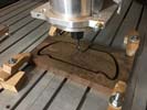
I recut a bridge blank and will also be machining the recesses for the hipshot units and other features while this is on the machine..
|
Left: I revised bridge dimensions and went ahead and cut a new bridge blank. I will probably go ahead and machine in some of the location features based on the new bridge units. Right: Updated machining file for the bridge is now done including recesses for the tuner units and holes for piezo wires and retention. |
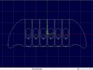
THis drawing (from Illustrator and inported into my CAM software) will allow me to get the bulk of the work done to the bridge. There will be more shaping and probably inlay but those will be seaparate operations.
|
|
I want to maintain as much flexibility in sound sources on this bass as possible.
|
Left: After some discussion with my suppliers I'm going back to these Hipshot bridges. Main reason is that they permit piezo due to removable saddle inserts. Right: I received the Hipshot tuners which will allow me to use piezo saddles and combine those with an internal pickup system also! Should be awesome! |
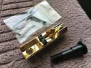
I now have the Hipshot gold hardware that will aloow both pickup systems to run in the instrument.
|
|
|
Left: Some more work going on right now to the neck and headstock. I will be attaching sides to the neck soon and want everything ready. Right: This is the layout of the bridge based on the Hipshot string retainers. I am going to cut a new bridge blank based on the dimensions of these units. |
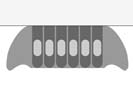
The other design of Hipshot bridge units offer more flexibility in terms of using piezo signal sources so I am leaning in that direction for the hardware selection.
|
|
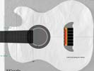
Bridge geometry established, need to cut one and see what bridge height it yields so that I can settle on a neck angle.
|
Left: I have a formula for the bridge geometry based on the smaller Hipshot (than ABM) hardware units. I'm going to cut a bridge and see how it looks. Right: I did the first pass on cutting out the bridge piece to see how it would look. I'll cut this out and try it on the instrument and see how if looks/fits. |
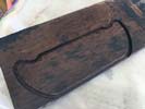
This is a test bridge but it is sized for the top of the instrument and the spacing and length of the bridge units so it may well be the one. I want to try it in place and see what I think!.
|
|
 |
Left: I chose to use this wood because it is such a good match for the top plate. Darker but with a little of the same colors inside - really nice. Right: Just another photo of this piece of wood - hard to photograph but it is really beautiful and very hard! Perfect for building a good strong bridge. |
Hard to picture this stuff - it will be dark but will have hint of the amboyna wood in it too..
|
|
In order to attach the fingerboard to the top plate I need to make sure everything else works into place. The location where the body and sides meet is fairly critical in this formula.
|
Left: The ebony I had for the bridge blank wasn't quite large enough so I am considering these two woods. Both are beautiful. Right: In this photo I am aligning sides with the top and back incase I need to re-bend sides just a little bit for the best fit. Might need a couple of small tweaks but not much. |
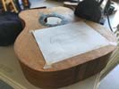
Checking geometry of top and back against the bent sides. If they have relaxed a tiny bit I will r-bend to fit before I start joining it all together!.
|
|
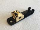
After looking at at trying a few options this very efficient solution from Hipshot will work best in our hybrid bridge assembly.
|
Left: The actual bridge units I received from my supplier were even more appropriate for our bridge as they have a black stainless steel base - they will look more discrete on the bridge assembly. Right: Sanding around the back and top plates so that they are consistently shaped with sides - this will help with upcoming assembly work. |
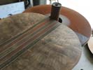
I'm working on both the top and the back panels right now to get them and the bent sides to a common size for assembly purposes.
|
|
|
|
|
|
|
|
|
|

