|

I thought I would put up a photo of the bass inside the case. This was a GUITAR case to begin with but for a headless bass we needed a case several inches smaller than a standard bass case. I had to re shape the entire lower section to fit our custom bass.
|
Left: Doing a couple of last minute adjustments to the instrument before I get is packed and ready for shipping put there in the big bad world Right: I had to modify the shipping box to fit the size of the case but got that part done. Now trying to get a few glamour shots of the instrument before it leaves here!!!!. |
I thought I would put up a photo of the bass inside the case. This was a GUITAR case to begin with but for a headless bass we needed a case several inches smaller than a standard bass case. I had to re shape the entire lower section to fit our custom bass.
|
|

I worked my way around the edge of the vase to finish off all of the edges and now I am done!
|
Left: Got all the perimeter binding done and the case is now officially converted for this bass. I've never modified of re-lined a case before - a bigger job than I expected. Right: Case with the bass sitting comfortably inside it. I am happy that I have now got this task done! I'm going to double check bass setup and look at suitable packing materials. |

I thought I would put up a photo of the bass inside the case. This was a GUITAR case to begin with but for a headless bass we needed a case several inches smaller than a standard bass case. I had to re shape the entire lower section to fit our custom bass.
|
|

I clipped the material fairly close to the finished edges and now have to create a nice clean edge around the perimeter.
|
Left: Just have the edges to do now and I'm done with this job! I have to glue and tuck the edges into a very small gap aroud the edge of the foam interior but it should be comparatively easy. Right: Finishing up the edges around the case interior and I can call this job DONE! It's a little tricky to get the edges nice and neat like this - just being careful as I go. |

II'm working around the edges with adhesive and scissors and many other tools to finish off the perimeter of the case lining and call this complete.
|
|

Surfaces and sides just about done - now have to trim and finish the edges.
|
Left: Almost done here with the surfaces and I will be trimming the fabric and ebbedding the edges into the structure of the case. Quite an elaborate task and will be glad when it is done. Right: Case almost complete now (it has been quite a lot of work because the material needs to be attached very carefully to avoid problems. |

I just have the upper edges to do - SO glad this is almost over.
|
|

Almost done with the flat lower surfaces - moving on to the sides as fast as gluing and clamping will permit.
|
Left: I am happy with the lining results so far - it should look very nice when done. Have most of the lower surfaces lined now and when the adhesive is set I will work my way around vertical surfaces. Right: I had emergency business out of town but brought this case and another project with me so I could keep things moving. |

I have all the surfaces attached and I am now fitting teh edges of the material into the perimeter of the case structure.
|
|

On as headless 6 string with a brass nut the work on the nut ideally requires disassembly and reassembly of the string retainer for each adjustment.
|
Left: While I am working feverishly on the case features I am also refining some of the setup elements on the instrument. I revisited the nut slots to get the best proximity to frets. Right: Working around the case on the vertical surfaces. I'm doing as much as I can in each gluing session. Looks good so far. |

I'm now working on the vertical sides and the little storage area - getting close!!!!.
|
|

I'm converting a guitar case to a headless bass case so there is a lot of work to be done in the conversion. It all pretty much fits now - big chqallenge is getting the overlay fabric on to make it look complete.
|
Left: I have been putting a lot of my time into the case to get it ready for lining and thereby completing this project. I'm almost done with the inserts and I am cutting the lining material. Right: This is the first pass with the new (hopefully better) adhesive that bonds better with the fairly thick fabric I am using. More pics coming soon. |

Started with the base of the cavity on the flat surfaces. I'm working in sections to keep control of everything..
|
|

The case requires a lot of my time - originally it was by removing areas to change it from a guitar shape to accommodate the bass shape. Then I had to cut numerous foam pieces to create the actual shape of the body of the bass inside the case. I'm almost done with these additions which requires a lot of material removal, shaping and gluing and clamping.
|
Left: I'm busy securing all these case components into the spaces in the case so that I have a nice consistent body shape and a combined flat surface onto which I am attaching the material! Right: I got all the modified pieces installed in the case and I am now working on getting it ready for the lining cloth and we will be done! |

I'm getting hold of a special glue that allows fabric to adhere to various surfaces (including itself) without bleeding through and marking the outer surface. I will be starting by lining the lower flat surfaces and molding the fabric up around the new sides I have created. Strings are off the bass for a final clean and check.
|
|

Since I had to cut, slice and dice the inside of the case to make it suit a 6-string bass rather than a guitar, I am finishing it all off with a nice plush matching blue material.
|
Left: Well I got the "thumbs-up" from my trusted electronics guru that the controls on our bass are all working. This is good news for me as I can focus now on getting everything ready for shipping! Right: Filling little gaps in the case packing so that when the lining is applied it will look continuous. |

All these inserts have been glued in based on the actual shape of the bass.
|
|

Knobs are on all the controls - it looks complicated but you get used to it all pretty quickly.
|
Left: Been on the road today dealing with several tasks one of which was to get this bass over to my electronics guy to allow him to test it for me. I will have updates on this and other info very soon! Right: While bass is being checked I am doing some more work to get the case ready - trying to co-ordinate this with everything else! Pictures coming. |

The lady who said she'd do my case ended up not able to help so I had to do the internal work myself. Basically the case is a guitar case and I had to open it up and re-shape it for a six string headless bass. I has to cust ome internal parts out and then add some structural foam matching the new shape. This photo was taken a little while agp but shows some of the conversion work.
|
|

I'm glad I had another set of gold knobs on hand - I didn't like the other ones.
|
Left: I swapped out the three sets of stacked knobs for these in the photo which are less tall and tend not to bind with each other for a better feel for the player. ! Right: While I am working on other stuff on the instrument I have the string retainer off to refine a couple nut slots and double check frets. |

Very glad to have my electronics guy's ok on the wiring so I am doing a bunch of last minute jobs to get the bass playing as well as possible while I finish up the case work.
|
|

Shipping is a tiny bit more complicated but I am working on getting it all set up.
|
Left: I am looking into the shipping options for this bass so that it can travel to its customer safely. More info on the last stages of completion in the next couple of days. Right: Well I lost a year of my life today when I plugged in the bass and got only some sounds. I discovered after panic-ing that I had no batteries in it so hence no active signal! |

Ran out and bought a bunch of new batteries!.
|
|

I am working on some of the custom details on the insude of the case so that the bass fits snugly in there. It;s messy so I will post a shot of the beautiful finished interior upon completion (I'm almost done with it).
|
Left: The case is a VERY strong and rugged one and will definitely protect the instrument during its life on this planet. Some time ago - I had to re-cut the interior shape to match the geometry of this bass. Right: I have the stacked knobs attached after reducing the length of the shafts for a much better fit. Looking nice. |

This is the bass with all the regular and stacked knobs attached. Once you get use to them all they make sense.
|
|

I am working through all the adjustment t get the instrument correctly set up. Some adjustments affect others so you have to do it all at the same time and go round a few times. So far so good - almost there.
|
Left: Instrument looking and feeling much better after nut slot work has been completed. I am also going to raise the pickups just a little to optimize the sound and balance. Intonation has also been done. Right: This may seem a strange picture but in order to optimize the knob heights I am taking a little material off the top shafts. |

Pot shafts are always a little longer than the net height of the stacked knobs and in the case of this instrument it looks a lot better with the stacked knobs just a little lower.
|
|

I am adjusting pickup heights, bridge saddles, intonation, nut slots, all at the same time to get everything working together.
|
Left: Some adjustments being done to pickup heights, bridge saddle heights, intonation etc. Everything coming together at this stage to create a complete instrument. Right: It was a fairly complicated process to get the nut set just right - file a little - put the hardware and strings on - test - take strings and hardware off and repeat!!! |

Nut was a little work-intensive to set up - I'm working on the last string to get it a few thousandths lower so that everything feels right!!!.
|
|

Working on checking the fret level condition which I have to do after nut slots have been set for height.
|
Left: I'm doing a dressing of the frets to make sure our gold frets are nice and level for the best playing experience. This helps me in the process of setting the neck and intonation.. Right: The frets have been carefully leveled at 600 grit to ensure there are no high spots and I have also followed up by polishing them with fine steel wool. |

Polishing with fine steel wool makes sure the finish on the frets is nice and smooth plus it helps remove any remaining finish on the metal.
|
|

I need to take the string retainer off to file the nut slots so it's a lot of dis-assembly and re-assembly to get the nut slots down to the right level.
|
Left: Nut slots are where I want them and the instrument is playing nicely. I'm doing some adjustment to intonation and the string heights at the bridge to optimize everything. Right: The LED lights look really nice - I have been so busy I forgot to get a photo of what they look like. One of many interesting features of this bass guitar. |

The LED lighting looks really impressive and matches the colours of the instumrnt.
|
|

The bass is coming together nicely - got the bridge pretty much dialed in and now setting truss rod and intonation..
|
Left: I'm in the middle of doing a setup on this beautiful instrument to get everything playing the way I wnt it on all the strings. I will have more photos as I get it ready! Right: I tightened up all the retaining nuts for all of the controls and added the knobs to complete the control layout. This bass has a lot of onboard sound capabilities. |

Knobs are on all the controls - it looks complicated but you get used to it all pretty quickly.
|
|

Almost done with the nut work and next will be making sure truss rod is properly tensioned and bridge units are adjusted for intonationa and string height.
|
Left: 2nd pass on the nut but we are getting close and I am looking forward to playing this bass to test out its capabilities. Since it's a brass nut it takes a little more careful filing to get the material removed. Right: I'm checking and tightening up all the control locking nuts on the face so that I can add on the gold knobs. |

I have a few gold knobs to add to the instrument but first I am checking the locking nuts on the potentiometers.
|
|

I can now move on to setup procedures, first of which is the setting of the nut slots.
|
Left: I am moving on to other details on the bass - mainly the setup of the brass nut so that strings lay just right on the fingerboard. Sou dplay very nicely when this is done. Right: Right now I am filing the nut and re-testing the action. Means removing the strings a few times but it's a necessary job. Want it playing nice! |

On a headless bass it's a little bit laborious setting the nut slots as you are so close to the string retainers. It means that the strings have to come off after each test but it will be worth the effort.
|
|

Got all the LEDs connected together and to the ground system which is the end of a very long road. There are a couple of wires I need to secure down but it;s basically done and I can move on.
|
Left: This photo shows a completely connected control cavity! I am amazed all this stuff did actually fit in there but very happy that it did. VERY happy that this section is complete! Right: This photo shows the bass with both cover plates successfully attached to the two cavities. It feels very good to see this done - moving on! |

Both covers fit on after all that content! Now I want to refine the nut slots so that we get the bass playing as nice as possible.
|
|

It's not that there were many terminals to connect but each one had to be carefully shielded and attached with resistors, there shouldn't be much physical strain on any of the connections and they should all be re-inforced for integrity.
|
Left: LEDs are wired up - I feel like celebrating but I have to tidy up these wires and ground the two end cables, then make sure the lid fits on as it should. Still, an encouraging moment! Right: I have been working on getting the LED assemblied contained and secured within the limits of the control cavity. Just about there. |

I have tested the lights on all the LEDs and they are working. I made space for the assemblied and got them secured into the cavity.
|
|

Terminals on LEDs have been reinforced.
|
Left: I added some silicone to the LED terminals so that they stay solid through the wiring and installation process. I've seen these terminals snap off and this will prevent that fom happening! Right: Connecting wires to LEDs so that we have lighting. I can't pack all the wiring and fibers etc until everything is connected and tested - only 2 left. |

The end is in sight!!!!.
|
|

All 4 LEDs have been attached and I can now work on wiring up the power supply to make them work!
|
Left: OK - all the fibers in the bass have their LEDs fixed to their polished ends. I now have to add a little bonding material to the LED terminals to strengthen their joints before I connect wires and resistors. Right: Im in the process of connecting the 4 LEDs to the battery power incorporating the right resistor values. |

Connecting power to LEDs and also reinforcing the LED terminals which are always weak. I'll silicone the terminals before they are locked in pace and all should be well.
|
|

I can see the light at the end of the tunnel!
|
Left: Two down and two to go - as expected these are a little labour intensive to set up but I want them to be able to last a long time. These were the worst two (largest bundles) Right: Almost there with the LEDs - only one small one to go. Once they are all in I will secure all four of them with tie-wraps so that they say firmly in place. |

Almost done! Looks like all four of these will actually end up fitting in the cavity. That would be great!!!
|
|

Each of the four bundles of fibers needs to be prepared in this way. The better the condition of the ends, the better they conduct light.
|
Left: Not a great photo but I wanted to show the trimmed, leveled and polished ends of one of the groups of LEDs. This bunch (side dots) is now ready for an LED attachment. Right: This is one of the Green LEDs conneted to its bunch of fibers. I have to repeat this 3 more times and then connect them all up to the electrical power. |

I used surgical tubing and shrink wrap to bond the components together and keep all the light contained.
|
|

I have all the fibers separated by length according to how they will be grouped with LEDs. Feels a little bit more under control now.
|
Left: You can see from this photo that the fibers are now much more under control. I have them all grouped by color/location so we are getting there! Right: Just wanted to report that I got the blue LEDs in and attached to their respective fiber optics. Moving on to the green ones working with the space that's left. |

I have to identify the end location of each of the fibers so that I can group them correctly. Easiest way is to light them up and label accordingly.
|
|

Bending the fibers allows them to stay in place as I get each set attached to LEDs. They are hard to work with but the more you get done the less frustrating it gets!.
|
Left: This crazy setup with the aluminium foil is to allow me to apply heat to one area without affecting neighnouring areas in order to slightly bend fibers. Right: Testing LEDs - the greens I have are really good. I'm working on getting there installed first. Probably do green for regular dots and blue for 12th and 24th fret locations. |

There are LOTS of LEDs on the market but some are much brighter than others. I'm selecting my best ones. Don't look at this photo too long - you will hurt your eyes.
|
|

I have to identify the end location of each of the fibers so that I can group them correctly. Easiest way is to light them up and label accordingly.
|
Left: Anxious to get things done here - fiber bundles need to be carefully shrink wrapped in bundles and then have the ends filed flat and polished before assembly. Right: Fibers for 12th and 24th frets front and sides have been isolated. That was hard work, but I can assign and attach LEDs now to these 10 fibers and move on to the remainder. |

I have to get two things done here - one is to apply some heat from a heat gun to very slightly bend the lower group of fibers and when that's done cut this group to the same length (the ones with the red sleeve are the green dots on the front of the fingerboard.
|
|

The red LED lets me test signal on different parts of the switches - this switch will be controlling two separate sets of LEDs.
|
Left: Wired up and tested the power supply for the LEDs so I can now hook up the correct resistors and check my light sources. Doing blue and green like the instrument colours. Right: OK, the selector switch for the LEDs is correctly wired and re-installed intpo the instrument. I'm getting closer! Now I have to connect LEDs to fibers! |

It's complicated to make am om-on-on switch do some of the things I need it to do. This one will control both the front and the side lights as well as having an off position.
|
|

Looks easy but it's not! I have separated the fibers that go to the 12th and 24th frets on the front and side. I'm now deciding on LED sizes and where to cut the groups of fibers for best results.
|
Left: I now need to isolate all the fibers from 12th and 24th fret areas. Once this is done I can decide on how to group the fibers. I will then have to cut them to best work in cavity space. Right: I have separated F12 and F24 fiber bundles and am now pairing them up with the appropriate LEDs so that I can get those components connected! |

Looks easy but it's not! I have separated the fibers that go to the 12th and 24th frets on the front and side. I'm now deciding on LED sizes and where to cut the groups of fibers for best results.
|
|

I color coded the individual fibers so that I know where they emit light on the fingerboard or side dot area. It's a VERY difficult job as I have to take great care not to break these fibers. They will be strong and solid when complete but delicate when loose and it takes a LOT of careful handling to get this job done.
|
Left: I'm testing, cutting and bundling the fiber optic cables so that the actual LEDs can be places slightly staggered from each other and not be too crowded. Right: I have a set of LEDs that should suit the different bundles of fiber optics. I want the 12th and 24th frets to have opposing colours for them to stand out onstage!. |

I have my LEDs on hand and I will be getting the fibers prepared to attach to probably four LED units (as far as I can tell right now).
|
|

The good news is we are close. I will have to use probable 4 or 5 LEDs in the effore to distribute lighting to all of the front and side fiber optics. The challenge is making it all fit in the remaining cavity space.
|
Left: With the electronics and associated wiring packaged as well as possible into the cavity my challenge now is to connect up all these fibers to LEDs in the free space that remains. Right: Right now I am using a light to identify individual fibers and group them (front, sides, color) so that I can make decisions on how to assign to LEDs. |

I will need to know where each fiber goes so that I can attach the LEDs correctly. Then I will cut them to specific lengths and prepare the ends.
|
|

This is the portion of the MIDI wiring behind the output plug. All connected to its board and various controls and ready for me to test output on a compatible Roland decvice.
|
Left: I have everything ready on the bass for testing Roland MIDI and my appointment to do that is tomorrow. I don't see any reason why it would not work - will be testing through a Roland MIDI system. Right: Bass is on my workbench getting a new set of strings attached so that I can do the Roland testing with a full set. |

NIce to see a picture of this bass that's not a shot of the wiring system!! I've been pushing hard to get it into an electronic and physical condition that will permit me to do a proper test on the Roland package.
|
|

Happy to see all thewiring packagedinto the cavity. Still need to squeeze LEDs in there but will do that after the MIDI output has been tested.
|
Left: Just wanted to post a picture of the control cavity with the MIDIwires connected. This is quite a bit beyond where the wiring has ever been before and it's solid enough for me to see if I can get it tested on a Roland system. Right: I got all the critical parts fitted in and I have an appointment to test out the Roland components! |

Working on getting the two plugs connected to the body for testing purposes. Also working on the same parts on the inside so that they are secure and stable.
|
|

Current status of the internal wiring - muchcleaner looking and still more to take care of - but looking good.
|
Left: I don't know if the difference is very apparent (I think it is) but got a great deal of the loose wiring tidied up and grouped and stabilized inside the control cavity. Right: I am now working on the MIDI wires. I already connected up the wires to the output plug so now it's more of a case of packaging the wires in the best way possible. |

Making progress in the control cavity, working on all these MIDI wires now.
|
|

Since some of the components had to be unmounted for testing I have to get them back in place and tidy up the wiring.
|
Left: Our bass has spent a little time at my electronics partner's lab and he checked pickup tapping, preamp function, and all other non-MIDI controls. He says they all work fine. Right: Since I have clearance on the non-midi components I can now work on getting the Roland output connected and tested. Working on the wiring. |

The non midi wiring is getting packed and secured in place and I now need to take the MIDI wiring from the card (all those wires on the left) and package them in teh cavity so that they are out of the way and connect to the MIDI output..
|
|

Got everything working except bridge pickup so I have to go back in and see what's going on.
|
Left: Well - latest test showed mostly success. I got a good sign through the Audere and was able to jump between active and passive modes. I got a good pickup signal from the neck pickup but none from the bridge pickup so that appears to be my only small setback. Pickup tested fine earlier so it must be a terminal or grounding situation that needs fixing. Problem is I have to pull a lot of the out of the cavity (and possibly switches to access those areas! |
|

Nice to get a chance to get one of the covers back on.
|
Left: Enough wiring has been organized so that I can try to get the outer cover back on. The only issue is at the every front where all the wires exit, I need to make the wire clearance slightly wider so that all the wires pass under the lid and the lid snaps in place. I will do some small adjustments to the back of the lid and also to the grouping of the cables and everything should work out fine. I'm now going to connect batteries and test for output signal. |
|

The little board for the common ground wires is done.
|
Left: This is the grounding PCB with all its grounding wires collected in one place. I'm also adding some liquid electrical "tape" to the backs of the connections to strengthen them and make sure movement doesn't compromise their connections. You can also see in this picture that the board has been attached to the cavity wall with a couple of screws so everything is nice and rigid. The wires will be tie-wrapped also for safety. |
|

Now doing the careful arrangenebt and securing of internal wiring.
|
Left: Wiring cleanup has begun - I am starting at the PCB end and working my way towards the output plugs at the other end of the control cavity. The challenge right now is leaving enough space for a few LED connections to the fiber optic cables. As I collect, fold and tie these wires together that will become more obvious and I'm fairly sure there will be enough room. The wires are pretty flexible wheras the fibers are not at all! |
|

All wires taken care of - once I tidy things up I will connect the Roland MIDI outlet so that I can start testing.
|
Left: It may look like an explosion in a spaghetti factory right now but I have succeeded in connecting all the wires connecting everything to everything in this bass. I will do some cleanup not only so that it looks tidy but so that everything can fit in the available space given that we have a few LEDs and fiber optic connections still to set. However - this is all significant because it permits testing of all the functions built in. |
|

More connections, installed Rolabd 3-way switch.
|
Left: I now have the Roland 3-way switch installed in its location and it is connected to the Roland board and to the momentary switches per Roland wiring diagram. I also grounded the negative power feed for Roland power to the common ground on my little circuit board. Lots of wires in there that need to be tidied up but I want to do that when everything is connected and I have no remaining wires to deal with. MID feed is next. |
|

Getting close to completion here - the remainin 9 wires are mostly connections between components which, although critical, are not that hard to connect up..
|
Left: I have only NINE wires left to connect (and probably 50+ to route tidily to their destinations) but that feels good compared to where things were not too long ago. I now have power to MIDI and pream connected and two tasks left. One is to get all the Roland wires to the MIDI output plug (not a small task) and the other is to connect LEDs and poer to the Fober optic cable groups so that everything lights up the way I want it to. Wish me luck. |
|

Everything looks a little crazy right now but it will look so much better when the wires are grouped and tie wrapped.
|
Left: I have now connected power to the Audere system and also power to the Roland system. This will enable each to do its own independent job. I now only have wiring to connect to link the Audere output to the Roland system as a mixed input. Once that's done I tidy up all the wiring so that it takes up as little space as possible and I can then connect the MIDI cables from the Roland board to the MIDI output at the back of the instrument. |
|

Circuit board doing its job - may have a couple more grounds to add but this takes care of preamp, plug and pickups.
|
Left: Got most of the grounding wires attached to my little board and that allows me to tidy up the grounding wires and get them out of the way of all the Roland wires that need to be run from the circuit board across to the MIDI output jack. My whole goal in this wiring process has been to allow room for all these wires (and subsequently LEDs and fiber optics), but the primary objective is to get all this hardware to work happily together. |
|

Now working on Roland connections to and from the 3-way switch and the circuit board.
|
Left: All the components are installed inside the instrument and I'm right now resolving as much of the Roland wiring (which connects to many areas) and finishing up all the grounding wires. I also got the post coil tap pickup signals connected to the Audere and now I have to connect the putput plug and the related power and grounding wires to the right places. Not easy work as it is all so small and compact but looking good. |
|

I'm consolidating ground wires on a little home made circuit board.
|
Left: I have several ground wires from all the different components in the cavity and I decided it was best to use a common connector which I made out of a circuit board. This allows me to get all the grounds collected on the same area and olly have one common ground wire connecting to the cavity shielding. It helps me keep track of everything and creates a neater end result. Once I have them all on there I will fix it to the side of the cavity. |
|

I have a number of grounding wires, two going back yo Audere unit and the rest to the common ground..
|
Left: Roland pot re-connected, wires packed away and now I'm going to inter-connect all the common ground wires. I can't add the rest of the Roland stuff until I have all these wires hooked up and tested again on the magnetic signals. Once that's done I'll connect the Roland to the output, connect the Audere to the Roland and test again and I do not see any reason things shouldn't work. I just want to maintain a record of this work. |
|

It's a detailed and tricky process but absolutely necessary in a situation like this.
|
Left: A lot of the wiring involves extending fine cabling to allow separate components to hook up to each other. I'm extending the wires connecting from the Roland board to the Roland potentiometer so that I can tuck these wires in behind the other components and keep things not only tidy but constrained and secure, and free from movement that we don't want in a coplicated and busy control cavity. |
|

There are probably 100 wires in this cavity and I need to make sure they are all correctly connected, secure and carefully tucked into all available space.
|
Left: I got six more wire connections established, this time related to the Roland hardware, and tie-wrapped into the back of the cavity. Each one means less to deal with on the surface and they should not need to be disturbed again. I now have another six or eight common ground wires to deal with and that should really make a difference. I'm trying to leave as much space for LEDs as I possibly can. It's a big job but it's getting there! |
|

I'm almost done with the wiring diagram as I move through this maze. One Roland wire to assign and then I rub battery power to everything.
|
Left: Very important to keep a running and current diagram of the complexity of this wiring setup. When all the wires are installed you can't really see where they all originate from of where they go so this is my only reference. I'm in the process of re-soldering a few wires I had to cut to re-route and also integrating the Roland system into the Audere circuitry. Everything seems to work individually - just ahve to make them work together now! |
|

Definitely getting there - I can see the light at the end of the tunnel!
|
Left: I'm routing wires past the back side of the preamp module and also fixing the module in place. This will allow me to tidy up the preamp wires and get the potentiometers installed with their wiring cleaned up and as compact as possible. That gives us a bass with coil splitting and a 4 band preamp and active/passive capability installed. With that done I will carefully install all the Roland components and wiring. Sounds easy (laughs to himself!) |
|

I can't run all the Roland wires until all the other wires are packaged and secured
|
Left: The biggest challenge in this cavity is making room for all the wires. The Audere preamp has a lot less so most of that is manageable and helps beyond description. The Roland unit has a LOT of wires that have to go to the MIDI output of the instrument. Those wires (20 or more) have to pass by the switchig area I have been working on without getting in the way of verything also and allowing the cover to be attached. That's my next challenge! |
|
Choosing the best location in the cavity for the Audere preamp module..
|
Left: I had a couple of options on the placement of the Audere processing board but settled on the forward corner behind the fiber optics. I'm doing a little work to seat the pickup wires behind the preamp so I made some spacers that help fit the board securely in place. There are a lot of wires running from this area but a lot of them are already connected to the potentiometers. I'm connecting pwer to the unit and hooking up the pickup outputs. |
|

I got some work done to the pickups to raise their adjustment a little to match sting height. Worked out fine - now back to the control cavity.
|
Left: I did a little more work on the pickup seats to extend the range of the pickup adjustment travel. I wanted to make sure we will be getting the most from these pickups based on being able to set them at the perfect height below the strings. That is now taken care of and allows me to get back to the preamp and its fitting and connecting. I just finished re-assembling the pickups so I can safely flip the instrument over again and work on the back! |
|

Choosing the best location in the cavity for the Audere preamp module..
|
Left: I now will be installing the Audere system into the cavity. I am fairly sure this will be the best location for the preamp module as it keeps it out of the way of the fiber optics and the various potentiometer locations. I will get it locked in place and then get the pots installed into their respective holes. I have to remember these will also be a million Roland wires after this but hopefully it will all be easier than the previous configuration! |
|

CLittle bit of adjustment to pickup height adjustment.
|
Left: In order to get all the little tasks done to get this bass ready for shipping I am working simultaneously on the front side where I decided to revise the adjustment height for the pickups as they needed to sit just a tiny bit higher. I'm in the process of making the recesses for the screw heads a little deeper than they were and changing the support material inside. With this done I know the pickups will end up in the best possible place. |
|

Coil tap switches working and feeding pickup signal throug to their respective output wires.
|
Left: I may be putting up more detail than necessary here but it's always helpful to document progress. I'm making note here that I ran the bass with strings attached and the pickup outpus run thrugh the coil tap switches. That way I was able to test and verify that the pickup signals were coming feeding through the 3 way switches and that the coil tappingfunction on each appeared to be functional. Now I can attach the Audere unit!! |
|

Two coil tap switches are wired up and installed and wiring has been consolidated for space saving.
|
Left: This is the two coil tapping switching units wired into the instrument and packaged as small as the wiring will safely permit. There will be a lot of Roland wires running past this area soon and keeping the soldered connections strong and compact is the only way to go. These two switches are connected the each pickup on one side and provide post-switching sound on the other side which then connects to the preamp circuitry. |
|

Installing the coil tapping switches prior to preamp installation.
|
Left: Each toggle switch needs to be wired so that the connections have solid integrity. I have gone to great lengths to make sure that is the case and am now installing the coil tapping switches individually into the cavity. This provides me with post tapping pickup output signals for each pickup which I can now route to the audere system for post processing. All fairly tricky stuff that demands a careful and methodical approach. |
|

Making sure the connections under the most stress are REALLY solid as I rebuild the circuitry.
|
Left: Catching up with some of the photos on this project - first thing I did following the old preamp system removal was re-establish solid connections on the coil tapping switches so that I didn't need to worry about their integrity as I packed other wires around them. These sit deepest in the cavity and once other stuff goes in, they are the hardest connections to get to! These will now be connected to the appropriate pickup wires to complete this section.
Double checling connections before Audere and LEDs go in.
|
|

As soon as the new preamp is fitted and tested I will be installing the lighting.
|
Left: I have a collection of colored LED lights that I bought for this bass. I will most likely use blue and green as they match the colors of the instrument. Right: In the process of reconfiguring for Audere I am being careful to check existing pickup, switching and Roland connections in the process. |

Double checling connections before Audere and LEDs go in.
|
|

I heard that Audere did get the parts they ordered and are building the preamp on an expedited schedule for me.
|
Left: All good with Audere -I'm now just waiting for notice of completion and shipping and I have my electronic workbench cleared for some action when the package arrives! Right: My electronics guy was kind enough to remove the existing preamp system in the bass so that we can evaluate space for new content. |

The previous preamp system has been carefully removed from the cavity. Working now on consolidating some of the exusting wires in preparation for the new preamp install.
|
|

We are about to remove the existing preamp and all the related hardware so that we can solidify the pickup, LED and Roland content and prepare for the Audere kit.
|
Left: This pic was right before the existing preamp hardware was surgically removed. I am hoping the end result of these changes will be MUCH cleaner. Right: The surgical removal of the existing system required some care as so many components were inter-connected. Most if it is now done. |

Between my electonics associate and myself the removal of the preamp needs a great deal of care - we don;t want to damage the original by compromising any of the wiring.
|
|
|
Left: The Roland GK3B seems like a great system. The external kit is a bit bulky but since we are working with the internal kit it will be discrete. GK3B Test Right: We have a special potentiometer on order (which was apparently necessary for the East system too) so that the Audere system can be assembled. |

Audere toldl me to achieve the functions necessary they would have to order a special potentiometer. They found it and it's on its way.
|
|
Toggle switches all bundled together in the cavity.
|
Left: After some conversations with Mark and several with Audere we were able to come up with an electronic solution. We need a special potentiometer which we are ordering to add to the system. Right: The Audere system will save a LOT of cavity space and allow me to get all the LED components installed. |

Toggle switches all bundled together in the cavity.
|
|

Based purely on the phyiscal size of maximum control cavity versus minimum preamp and electronics size we have to use a similarly configured but much physically smaller preamp setup may have to be a classic based on teh complexity but that will save me having to drill another hole.
|
Left: We made a necessary decision based on available space, wiring integrity and common sense to redesign the internal electronics. Updates coming! Right: I have Audere working on a system that will provide me with active/passive control, passive tone and active Vol/Bal, Hi/Lo Mids, Bass/Treble + Z-Mode! |
Toggle switches all bundled together in the cavity.
|
|
Toggle switches all bundled together in the cavity.
|
Left: While my electronics package is being worked on I am working in the background on getting a strap made for my customer that matches the bass itself! Right: More wiring work being done - we are only getting part of the East preamp function to work and needs to do some detective work to isolate the issue. |
Toggle switches all bundled together in the cavity.
|
|
Toggle switches all bundled together in the cavity.
|
Left: I drove out of my electronics subcontractor and we tested the output initially through the 1/4 in jack output. We were getting sound but needed to replace a faulty switch. Right: Switch replaced and Mark is very confident of getting the bass back to me with all electronics functioning. |
Toggle switches all bundled together in the cavity.
|
|

It has been a hughe amount of work getting the electronics to work. I understand that the preamp manufacturer built a preamp system to such an advances level that they probably did not conceive of marrying it with another onboard system so we are breaking new ground here.
|
Left: well - it's been a long journey getting the electronic systems configured, fitted and working in conjunction with each other. I'm ready to pick the instrument up from my electronics subcontractor. Right: I have been driving to and fron from my electronics guy to assist in finalizing the electronics. |

So far have made 5 round trips to Palm Desert - 970 miles so far and more to come!!!!.
|
|
Toggle switches all bundled together in the cavity.
|
Left: This is my typical journey to my electronics associate - about an hour and 45 mins over a neighbouring mountain range! Right: Our wiring solution is looking good on paper but we have to physically test for sound and performance. Our current goal is to get that out of the way as soon as we can! |
Toggle switches all bundled together in the cavity.
|
|
Toggle switches all bundled together in the cavity.
|
Left: Once nice and encouraging thing that happened today -I heard from my electronics people that we now have a likely wiring/signal solution for connecting Roland and East systems. Right: Back visiting my electronics person for the 3rd trip. We are confident that the info we got from East systems will work. |

This is the bass on my partner's test bench after some significant time placing and connecting some of the final components and getting the wiring and signal feed strengths established for the Roland and East to work together..
|
|

Toggle switches all bundled together in the cavity.
|
Left: I was able to finally visit with my electronics subcontractor and evaluate East/Roland connections. We agreed on a plan to fix. Right: In contact with John East to find out the purpose of a couple of wires and to verify best interface between mag output and Roland mag/midi selector. |
Toggle switches all bundled together in the cavity.
|
|
Toggle switches all bundled together in the cavity.
|
Left: I'm putting another set of Kalium strings on the bass - used the first set for a lot of setup testing! Hoping to get my customer an endorsement there too. Right: We have been working on the interface between the Roland and East systems. We had to establish a dialog with East Systems so that we could work with them. |

We spent some time sending technical readings and measurements to East Systems in the UK. Our goal was to find the right way to make then talk to each other.
|
|
Toggle switches all bundled together in the cavity.
|
Left: Doing some adjustment work to the case to get the best fit for the instrument. Bass case was too large this one is a guitar case all I have to do it resolve the fit for the bass neck! Right: My technical guru was able to resolve a couple of initial wiring conundrums that weren't well indicated on the tech drawings! |

Everything looked good except for some system interface connections between Roland and East. We couldn't find a way to make them communicate with each other!.
|
|

The Easy System is destined to sound awesome. It is a little tricky to hook it up with shared capabilities to the Roland so I am working with my own electronics expert and exchanging info with john East to get the right wires in the right places since this is all very custom.
|
Left: I'm having the circuitry tested for integrity and to make sure the Roland system and the East System are talking to each other the way they are supposed to! Right: My electronics expert has much of the technical hookups and MIDI processing to test the MIDI output of the instrument. |
Toggle switches all bundled together in the cavity.
|
|

Just experimenting with the light sources to see what works best. This was from a green LED.
|
Doing some initial testing of fiber optic lighting. I'm verifying wiring on the 3 way switch that will be controlling the distribution of the lights. Right: I want to try and keep the LED connections as small and compact as possible so that I can still get the control cavity lid back on when I'm done!!!! |
Toggle switches all bundled together in the cavity.
|
|

I'm now getting ready to work on separating and adding lights to the fiber optic cables.
|
Left: Lots of wires and it's all a little scary. I now need to test the signals from MIDI and Magnetic pickups and make sure the blends and selections work correctly. Right: I'm taking the instrument to my trusted electronics associate to have a last look at wiring and the schematics before LED work is added. |

I am going to be taking this bass to my electronics expert to verify a couple of connections and test out the Roland system so looking forward to not thinking about these electronics any more!!!!.
|
|

I'm only slightly worried that the player will need a pilot's license to fly this thing!.
|
Left: Things are fitting better now - I'm amazed I got it all in there. 1000 thank-yous to my patient customer! We're close. Right: For anyone interested, these are three of the toggle switches, two are pickup coil tapping selectors and the one on the left is the East Systems active/passive switch. |

Toggle switches all bundled together in the cavity.
|
|

It was awkward but I was able to get the recess relieved just enough for the board to go into its place!! One more problem resolved!.
|
Left: Well - that was fun - I was able to grind out a recess to get the cables to cooperate. Need to tidy it all up now and keep things moving along! Right: I tidied up the area I modified and added copper shielding to the exposed area. the Circuit board is now to be fitted and connected per the diagram. |

My surgery to the cavity has been cleaned up.
|
|

This is what the cavity looks like with almost all the components in it. The issue is now getting the wires under control.
|
Left: Almost all the hardware is in the cavity now (except for jack socket which I had to temporarily remove) I'm starting to tie wires together to protect them from damage. Right: I need to do some hand carving to create just a little more room for these wires because of their long connection terminals. |

Not a major task but I will use a hand dremel to remove a little bit of sidewall so that these long terminals can clear the side of the cavity.
|
|

I have the Roland system pretty much set in the cavity and I'm now wiring up the East system so that all its connections are done.
|
Left: I tested sound from pickups through the selector switches and now I need to route that signal to the East board pickup inputs. Fortunately have a diagram! Right: I'm putting a new set of Kalium strings on this bass since I have used the first set for testing. I think they will sound awesome on the finished bass! |

I have a lot of confidence in Kalium strings and I am very sure they will compliment this instrument.
|
|

I knew the wiring at this end of the cavity would be very demanding because of the accumulation of other wires once I got to this latter stage. I extended the wires going from the pot to the board and got the pot secured into its hole in the cavity. It was a lingthy process - time for a strong drink!.
|
Left: This is the potentiometer for the Roland bass control which is the last pot to go in but the hardest one to fit because of space and wires! Right: Roland pot has been secured into the cavity and connected to the Roland board. I had to extend the wiring on this component connection too but done now! |

Roland volume not only connected to circuit board but also successfully installed under all the other wiring and hardware. I spent a lot of time on this part of the job!
|
|
In this photo the volume balance board is bottom right. Those connectors on the green area will receive the direct feed from the pickups through the coil tap switches. The board above that manipulates some of the control frequencies.
|
Left: The East system has a couple of separate boards that are used for manipulating sound. Those are being fitted in the cavity area. Right: The 3-way selector switch for the East System is now installed. Wires everywhere and it's hard to work between them all but these are the last few parts!!!!! |
Starting with the coil tapping switches then onto wiring for the LEDs. After that the output plugs and boards..
|
|

Starting with the coil tapping switches then onto wiring for the LEDs. After that the output plugs and boards..
|
Left: Got the last two East components fitted (was not easy) and I'm now working on the numerous connections for those. Right: I'm making some slight modifications to the case in order to allow the neck to fit. Body fit good but since it's a guitar case I have to scallop a little more for the neck and re-cover. |
Starting with the coil tapping switches then onto wiring for the LEDs. After that the output plugs and boards..
|
|

Volume Balance circuit board and the Mid control are ready to be fitted and in stalled. On the V/B there is a LOT of wiring so I will have to route these carefully.
|
Left: Next two East preamp components are the Volume/Balance board and the mid frequency control. These will be the last two for the East system. Right: This is what the switching looks like from the front. All of these are installed. Given the constrictions I think we ended up doing pretty well on the limited control layout! |

Although we have a lot of switches the layout os logical and belies the space shuttle wiring behind the scenes!!!!.
|
|

These boards are all test fitted and will soon be permanantly installed.
|
Left: Some more of the East circuit board components to be bolted into the cavity - we are almost at full capacity now. Little cramped working on the wiring but so far so good. Right: I am going to be shortening the fiber optic cables to place the LEDs in the part of the cavity with the most remaining space. |
i will have at least three LEDs working in the control cavity. Once all the wiring is set I need to cut the fiber optic cables back to a point where I can connect them with their respective LED units.
|
|

Output sockets, LED switching, passive tone, East System big board, coil tapping switches, Roland program switch now all connected. I know it looks like many of the other photos but a lot of the electronics have been connected!.
|
Left: Selector switches are now connected and I was able to install another of the East hardware components as I work towards the front end of the cavity! Right: Moving along - I'm using zip-ties to consolidate some of the wiring and make some sense of it all! Getting close to having everything connected!!!!! |

Starting with the coil tapping switches then onto wiring for the LEDs. After that the output plugs and boards..
|
|
Starting with the coil tapping switches then onto wiring for the LEDs. After that the output plugs and boards..
|
Left: Working towards the finish line - the electronics, as anticipated, are complicated and exhaustive because we have som many functions happening in this bass! Getting through it!! Right: My next task here is wiring up the two program selector switches and connecting them to the board and 3-way switch. |

Just succeeded in connecting the two program up down switches to their correct locations.
|
|

East Passive Tome control now part of the wired cavity. Next is Roland function switch.
|
Left: Here's our passive tone control fixed into its little space at the back end of the cavity. I can't locate the other East components permanently until I get these parts situated. Right: Got my little Roland switch wired up according to their color specifications to now moving right on to the next step! |

Got that Roland switch connected up according to the Roland diagram..
|
|

I will probably only need two green LEDs for the light - just making sure they all work
|
Left: The green LEDs are working great too. I need to locate them and cut the fibers so that they all meet in the right place in the control cavity. Will post a pic of neck with lighted dots asap. Right: Next challenge is to wire up this little red selector in the center. It is the Roland 3 way selector switch. |

This little red 3-way selector switch is part of the Roland setup. I need to get it wired up to a couple of sets of wires that go to the remote circuit board.
|
|

No one but me will ever know how much work it has been getting these components and wired fitted together! East board in next to LED selector, two output boards attached and now to add the passive tone!
|
Left: I am now fixing in the East system components. The hardest part right now is keeping control of all the wires and being VERY careful not to damage anything. Right: This is me testing out the LED lamps to make sure my in-line resistance is correctly calculated. I have a lot of fibers to illuminate! |

Testing my LEDs, this is one of the blue ones. I'm planning two sets of three LED sources, one set for side and one set for front illumination. HOPEFULLY I can get away with two for each set but I can go up to three according to my resistance calculations.
|
|

I needed to get the two output plus installed before some of the remainin components mainly because the related wiring is so extensive and runs all the way through the cavity.
|
Left: I'm now installing the output circuit boards and sockets and channeling the related wiring through the cavity. Wiring connects to both East and Roland boards. Right: These are my LED modules some of which will be supplying light to the fiber optic cables. I also have an assortment of resistors to add to the circuit. |

These LEDs are intens blue and green, and they will reflect the color of the bass. I'll probably make them all blue except frets 12 and 24 but I have a few options!
|
|

LED switch is wired up. I will add resitors and lights and test it next.
|
Left: These are the wires that are required to connect the LEDs from 9v battery through the 3-way switch. It feels great to have this task done - progress is good! Right: Doing a little drilling to seat the pickup adjustment screws just a tiny bit deeper in the pickup covers for a little more travel! |

I hate drilling a finished component on an instrument but I want to best the tops of the adjustment screws a tiny bit deeper into the tops of the pickup covers..
|
|

I'm swapping out the temporary screws for the gold set to match bridge and knobs etc.
|
Left: I'm now swapping out the eight chrome adjustment screws in the pickups I was using as temporary holders for the nice shiny gold ones. Right: fiber optic switch has been wired and I re-installed all the gold tuner units and double checked grounding continuity. I will soon be testing the Roland unit too! |

Getting those tuners back on after all that work in the clean room. Bass in back on my shop bench and I'm planning to get it playing notes as soon as I can!.
|
|

This is my revised drawing of the wiring required for the LED lights. Has to consult with a couple of experts on this!
|
Left: This is my wiring sketch for the 3-way switch that will be controlling the LED lights in the control cavity. Working on that right now!. Right: Got that LED selector switch wired and installed and also fitted many of the wired components in that area of the control cavity. Also connected common ground wires. |
Starting with the coil tapping switches then onto wiring for the LEDs. After that the output plugs and boards..
|
|

Working on getting the LED power supply established.
|
Left: In this photo you can see the LED selector switch and the battery connector I just added. The black and white are the power wires going to LEDs. Right: This is the case I ended up with after trying two other similar ones. I liked it because it is strong and light and I don't have to modify too much.. |

Of the three cases I had tested this one was the best overall size, weight and fit for a headless bass. It is actually a guitar case. Waterproof, very strong, good hardware and definitely gppd protection.
|
|

I'm fitting all the rear components and their wiring together so that the back end of the cavity has been completed. I still need power wires for jack socket and LEDs but the others are taken care of.
|
Left: Working on the next phase of wiring which is to permanently install the hardware from the two output plugs and forward. Right: I'm trying to get all components and wires installed from the bottom up otherwise I have no room or access to solder joints on the bottom level of the control cavity. |
Starting with the coil tapping switches then onto wiring for the LEDs. After that the output plugs and boards..
|
|
Starting with the coil tapping switches then onto wiring for the LEDs. After that the output plugs and boards..
|
Left: Just a quick note - ran output wires from each switch and tested the pickups and coil tapping. I got sound and hear the difference between the 3 settings! Right: In this photo you can see the two coil tap switches on the left, the 3-way Roland switch in the center and the LED selector on the right. |

Starting with the coil tapping switches then onto wiring for the LEDs. After that the output plugs and boards..
|
|

Very precise work to get these tiny wires securely attached, many of them in pairs.
|
Left: At the risk of boring the reader - I'm almost through the wiring of the 2 coil taps. Minute work requiring magnifying glass, strong glasses, really good light and PATIENCE. Right: Clipped wires as short as I dared to save space and have soldered them to our coil tapping switches and installed in their cavity locations. |
Starting with the coil tapping switches then onto wiring for the LEDs. After that the output plugs and boards..
|
|

There was a time when I never thought I'd get here - all switches and knobs accounted for and I'm ready to do some soldering.
|
Left: Last piece of the puzzle installed (that little switch in the Upper right corner). That's the LED switch that moved to make room for the two coil tap switches! Right: The final frontier - I'm wiring these boards and switches together to create sound in this monster. Being very careful and methodical. |

Starting with the coil tapping switches then onto wiring for the LEDs. After that the output plugs and boards..
|
|

The two selector switches for coil tapping being added. Space is incrediblt tight in there but hopefully we have planned correctly and it will all work out.
|
Left: The 3-way coil tapping switches need to be positioned, carefully cut for relief and installed. I think I have allowed for their placement in the cavity. Right: The additional internal work went well and I now have locations for both coil tap switches and the 3 way switch that will control the LED light selection. |

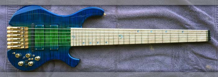
Damn = it really is a good looking bass - I have spent so much time on its insides I forgot to appreciate its outside!!!.
|
|

Switching diagram furnished by Norstrand - big help to me since wiring this bass is a complex task.
|
Left: I was a little confused by the pickup wire colors and what might be necessary from a wiring point of view to achieve the 3-way pickup switching - fortunately resolved. Right: Pickup wires shortened and connected to our 3-way switches. It helped a lot to get the wiring from Nordstrand. Now to install them. |
This is a very impressive hard case - waterproof, shockproof and very safe. Nice that it also has a blue lining!.
|
|

This is very good to know - have data on the location of the five connections on the East system which allow me to connect the signals from pickups (post coil tap) and to and from power supply.
|
Left: I found out part of the wiring I needed to know - the pickup inputs to East system and the power supply connections for the same active system. Right: This is the case I'm planning on using. Very high quality and although designed for doublecut guitar, the bass should fit with minor internal mods. |

This is a very impressive hard case - waterproof, shockproof and very safe. I had tried a couple others which were good cases but did not accommodate a 6-string bass neck well at all. Out of all my compact choices (Guitar cases because bass ones were just way too big) this one was the best fit on all levels!.
|
|
I added the 1/4" jack plug and its associated wiring plus the passive volume and the wires connected to that. They all fit around the big East board!.
|
Left: More electronics installed and I'm feeling encouraged. Worked on a East wiring diagram much of the day to make sure I has all the wiring connections correctly placed. Right: I'm going through all the wiring tomake sure Roland and East have all their connections - also have numerous others to do. |

I have some unknown wires to resolve on one of the East boards, plus hook ups for pickup coil tapping, power to preamp and LEDs, connections oto 1/4 jack and one tricky connection between Roland and East to tap mag signal.
|
|

Nobody on the planet is happer than me since I got all these wires routed around the back of the big East Systems board. That was hard to do but it's DONE!
|
Left: With the largest of the East System boards in place I was able to feed the 15 Roland wires around the end of it - had to carefully do this one wire at a time! Right: More East hardware going in and I was able to get the jack scocket wiring around the East board too! Also the Passive Volume. |

I added the 1/4" jack plug and its associated wiring plus the passive volume and the wires connected to that. They all fit around the big East board!.
|
|
I was able to cut and solder all the ground wires to the common ground of the control cavity. Good to get those out of teh way..
|
Left: East system going in progressively. I had to remove material from cavity and add more copper to make clearance for the big board near the output sockets for Roland wiring! Right: I wanted to get all the East System parts into the cavity so that I could see what space I had left for the two pickup switches! |
I was able to cut and solder all the ground wires to the common ground of the control cavity. Good to get those out of teh way..
|
|
I was able to cut and solder all the ground wires to the common ground of the control cavity. Good to get those out of teh way..
|
Left: Tuners back on the bass as I want to get strings on the instrument as soon as possible to test sound from both sources. Right: I'm adding two switches to the array whose purpose is to modify the coil selection from the two pickups. They will each provide series, parallel and full humbucking output. |

These are the two on-on-on switches I need to provide 3-way coil tapping on each of the pickups.
|
|

One o fthe first challenges with the space will be routing these Roland wires (13 of them) up and around the upper edge of the East control board. I may have to remove a tiny bit more material from the cavity - we will see.
|
Left: In this photo I am working with one of the largest East boards in an effort to run all the Roland output wires past the upper end so that they are safe and out of the way. Right: Now that I am working on the inside of the control cavity I can afford to re-install the six ABM tuner units back onto the body. |

Getting the tuners set back up on the top of the instrument. Apologies for the dust - did this in the workshop to save time!
|
|

Working from bottom up - doing the grounding of the copper wires to the cavity shielding
|
Left: Task at hand right now is to get all the copper grounding wires solidly soldered to the cavity shielding which is my common ground. Right: I got all eight ground wires shortened, cleaned up and soldered to the shielding in the control cavity. This cleans things up quite a bit - on the the next phase. |

I was able to cut and solder all the ground wires to the common ground of the control cavity. Good to get those out of teh way..
|
|

Text coming soon.
|
Left: Since it's time to get the remaining wiring done I need to get the neo magnets installed in the remaining two covers so that I can close them up. Right: Retaining magnets installed in battery and control cavity covers. I need to remove protective tape from one and add copper shielding to the other. |

GNeo magnets are now in both the remaining covers.
|
|

This should allow a good fit on the cover. I will sal the back before we're done but right now just want to get these wires under control!.
|
Left: This is the Roland board cover with the recesses machined out to create a little room for the wires to exit from the board. More assembly now. Right: Quick photo of the cover on the bass doing it's job retaining board and the many wires that run from it. One step closer to making sound on this bass! |

Happy to say I hav that circuit board area closed up and the cover fitted on!.
|
|
Great news - all these little MIDI wires have been extended - my eyesight may never be the same but this job is done.
|
Left: Starting on the East System install. I want to be careful as I proceed not to compromise any of the wiring and keep things as orderly as possible. Right: Cover marked out for some machining to create clearance for wiring coming off Roland board. I want to have this area sealed off and done. |

I have to be careful not to compromise the cover but I do need to cut out a little vertical clearance for the areas where the Roland wires bend 90 degrees to exit the cavity..
|
|
Great news - all these little MIDI wires have been extended - my eyesight may never be the same but this job is done.
|
Left: I did a little cleanup of the copper shielding in the control cavity before I start adding all the additional pieces of electronic hardware. Right: We are definitely getting there! I'm almost done with the Roland system requirements and connections and now preparing East preamp parts. |
Great news - all these little MIDI wires have been extended - my eyesight may never be the same but this job is done.
|
|

Those Rolaand wires add up to a pretty big bundle do I have made the channel between cavities quite a bit bigger.
|
Left: This is the Roland board area with the enlarged channel for all the connected wiring. I can now finish up this little cavity area and move on. Right: Although I have to wait until East System is fully installed (at least physically) I spent some time testing and grouping the fiber optics for LED connections. |
Great news - all these little MIDI wires have been extended - my eyesight may never be the same but this job is done.
|
|

I have three magnets to securely hold on the Roland cavity cover. We should never really need to go in there once the instrument is finished.
|
Left: I added magnets to the covers and Roland cavity so that I could test the fit and clearance of the wires especially in the cavity with the Roland master board. Right: The Roland MIDI circuit board is fully wired and connected and I have all the exiting wires grouped according to where they travel within the cavity! |

This is what the Roland MIDI board looks like with all its wiring connected. I will be able to package and isolate this piece in the separate cavity.
|
|

Some surgery needed between Roland cavity and the main cavity due to the collective volume of wires going from one location to another from the board.
|
Left: I removed the Roland board so that I could cut more material out of the transition between the two cavities. LOTS of wires! Right: I have to mark out areas where the wires need a little clearance (along edges) and then cut that relief into the bottom of the cover! |

I don;t want to have pressure on the wires exiting the Roland board so I need to cut a little relief in the back of the board before I can finally fit it. I also had to deepen the channel between the two cavities to accommodate all the wires!.
|
|

Roland wiring all on my diagram. Because East wiring and pots are solid state the connection between Roland and East may reaquire some research but so far so good.
|
Left: For anyone interested, this is my updated wiring diagram - it still doesn't include all the East wiring but Roland wiring is all accounted for. Right: I'm going to need power to everything so I will be connecting three battery terminals, one to each battery to distribute power to Roland, East and LEDs. |

One of three battery conections I am adding the thebattery cavity.
|
|

Getting all the wires connected to the board so that I can see what I'm dealing with space-wise.
|
Left: I have been using the instruction paperwork from the Roland hardware to get the main board wired so that I can fix the cover on that part of the cavity! Right: Had to cut out a little more clearance between the cavities to accommodate all the wires! Great to have this part of the wiring done! |

This photo shows all but two wires running out from the Roland control board.
|
|

I now have connectivity between the Roland output 13 pin terminal and the main Roland board. This is great - now to assemble all the other stuff!.
|
Left: Great news - the wires fit and I will be able to pack them into the lower sides of the control cavity. I'm very encouraged to get these parts conneted together - I can see the light at the end of the tunnel! Right: I'm now able to make some progress getting the Roland components set in the cavity. |
Great news - all these little MIDI wires have been extended - my eyesight may never be the same but this job is done.
|
|

Ugh!
|
Left: I'm about half way though all the soldering work. It takes a long time to strip these tiny wires, prep the ends, clean up, solder and shrink wrap. Some need done more than once. Right: DONE!!! MIDI output wires have been extended. Took all the micro-soldering skills I have to get it done! |

Great news - all these little MIDI wires have been extended - my eyesight may never be the same but this job is done.
|
|

This will be a super step forward and closer to being DONE. These two wire clusters are the main MIDI connection in the system and cables are too short. I was unable to locate longer versions on the internet so my only choice is to extend them. I'm using color coded ribbon to make sure I get everything connected correctly.
|
Left: I'm cutting and extending some of the MIDI cables a couple of inches longer so that I can connect the Roland outputs to the MIDI board. Very precise work - will be glad to have it all done! Right: These joints have to be as small and clean as possible. I'm actually adding 4 inches to the overall length. |

I am starting on what will be a tedious task. 28 solder joints - widh me luck!
|
|
Half a day's driving but I got what I needed to extend the wires from Roland socket to the circuit board!
|
Left: these are most of the wires that come and go from the Roland board. My task is to make them all fit, get the lid on and make sure there's clearance for the outgoing wires. Right: A lot more electronics in the cavity now. I am trying to asemble in order so there is room to move wires around and make connections. |
Half a day's driving but I got what I needed to extend the wires from Roland socket to the circuit board!
|
|

This is only party of the whole diagram. I want to get the board itself all connected up so that I can take it out of the firmula and concentrate on the other million cables!
|
Left: I'm reviewing the Roland installation instructions and identifying which sets of cables go to which inputs on the main board. Also working on cable extensions. Right: I have started working on the two main cable connections running from the 13-pin output boards to the main Roland circuit board. |

There are a lot of cables running from the Roland board to other parts of the control cavity.
|
|

I need to lengthen these cables (yes all of them) to reach the Roland board.
|
Left: These two sets of cables connect the boards on the 13-pin output to the main Roland board. I need to extend these about 2.5 inches. Right: ... and - here is the likely solution - I drove to my nearest electronics supply ceter and picked up connectors that will allow me to stretch the Roland cables. |

Half a day's driving but I got what I needed to extend the wires from Roland socket to the circuit board!
|
|

The volume/balance board, LED switch and mid controls are hard up against each other but the did go in. So far so good!.
|
Left: This photo shows how tight these components will be - the circuit boards, knobs and switches will be up against each other! Right: I'm hooking up wires to the selector switches and also starting to map out the paths to all the other East and Roland wires. Also establishing common ground location. |

I'm in the middle of charting out wiring paths so that I have a record for me, my customer and anyone else I need to sgare it with. More elements to be added but this should be our recipe for success!.
|
|

Switches are recessed on the back and now installed in place. Actually looks pretty good!.
|
Left: I got the three switches recessed a little into the back of the cavity in order to expose a little more of the thread on each one. Right: These are the switches which I recessed from the back and are now in their final resting places. Quite a tricky job and I had to re-apply new shielding in the cavity in those areas. |

It may seem insignificant but getting these switches in the last remaining space in the cavity was a BIG achievement.
|
|

I'm in teh process of installing the Roland program buttons and the three selector switches. These items sit on the lowerst level in the cavity so should be installed first so that the wiring can fill the space above.
|
Left: This photo shows how low-profile the Roland program buttons are so they will not get in the way of the operation of the stacked preamp controls. Right: Switch on the left will be the one that controls Roland features, the one on the right (lower) will control LEDs for lighting. 3rd one will be East System. |

Switches being installed, I may countersink them on the back just a little as they don;t have a lot of thread. So far so good though.
|
|

All holes established, and I am sure with knobs and switches in place the bass will not look as busy from the front as it really is inside! It's been a long day.
|
Left: I have now verified and drilled out the holes for the three selector switches. It was a fairly delicate job based on very limited space. Right: Test fitting all the components together. These all have to fit in the cavity in order for wiring to get run. Fiber optics and LEDs will have to work around everything else! |
Probably one of the most delicate machining jobs I have ever done - I hate nachining and already finished instrument - so many things can go wrong!!!!.
|
|

The existing East hardware only allows me a couple of very tight spots for the three switches. One is East active/passive, one is Roland related, and one is for fiber optic LEDs activation.
|
Left: The huge quest to fit a mountain into a molehill is almost resolved. After hours of testing with neighbouring electronic hardware these are the only 3 viable locations for the selector switches. Right: Electronics removed for drilling purposes. There is literally NO room for error or parts will not co-exist. |

I have already drilled pilot holes - I just have to drill to 1/4 to suit switch diameters.
|
|

I haven;t fitted the eselector buttons in yet but this photo shows their placement. They are very low profile so they do not get in the way of the knobs..
|
Left: I wanted to show a quick photo of the results of the recent machining and how the program up/down switches looked next to the knobs. They won't interfere because the are on very different levels. Right: The last holes to go into the control cavity are the three holes for the three toggle switches. |

Not much space left - but these are the LAST three objects to jam into the control cavity!!.
|
|

I'm setting up to cut two holes for the Roland selector switches.
|
Left: Bass now up on CNC for some extremely careful surgery. I can't afford to have the surface take any damage from a normal drilling operation. Doing the work here gives me the best chance for cleanest results. Right: Very very delicate operation creating holes for the Roland selector buttons! |

Probably one of the most delicate machining jobs I have ever done - I hate nachining and already finished instrument - so many things can go wrong!!!!.
|
|
Both outputs are set in the instrument - I just need to add retaining screws.
|
Left: I had to take the bass back to my shop to get the program switches and toggle switches installed in areas which are now free after East system install. Right: It has been decided on the location of the Roland program up/down switches. The holes will need to be very carefully drilled on the CNC machine. |
Both outputs are set in the instrument - I just need to add retaining screws.
|
|

Now ready to take this beast to my electronics guru. Will update as soon as I have news.
|
Taking this very complex musical instrument to my electronics expert in Palm Springs. I completely trust his abilities and we will work together to get all the internal parts connected together and working in harmony. There will be some custom cabling work he has to do and there may be a few calls back and forth, but it will all come together and I am glad we are here! I, along with my customer, am looking forward to the results. |
|
Both outputs are set in the instrument - I just need to add retaining screws.
|
Left: Adding neodymium magnets to the three back cover plates so that when I get the bass back I can test fit them and cut any relief necessary. Right: Good news is the bass is now strung up and adjusted close enough to yield the source signals for my electronics guy. It's been a hard journey but looking good. |
Both outputs are set in the instrument - I just need to add retaining screws.
|
|

I put Schaller locking strap locks on the bass. One on the upper horn and two on the back of the bass so it can stand safely when not on a dedicated music stand.
|
Left: Just wanted to show the bass with its strap buttons installed - so much going on electronically that I forgot to add these! Right: Working on the refinements of the nut so that I can get the strings on. My electronics expert will need it fully strung and tuned to test all the various output options on this bass. |

Both outputs are set in the instrument - I just need to add retaining screws.
|
|

Some tough choices here. I tried to locate a suitable momentary toggle for program up/down but could not find anything rated for the Roland specs. I have dcided to install the two program up/down buttons next to each other as shown. The two remaining toggle switches will occupy the remaining spaces in the cavity.
|
Left: Switch holes are set and I have to decide now whether to include the two program up/down push buttons for Roland or substitute those with a momentary toggle switch. Right: Re-assembling the tuner hardware which I had to remove during electronic assembly since the bass needed so much handling. |

Tuners going back on.
|
|

Very little remaining room to play with in the interior of the control cavity. I will end up using ALL the available space.
|
Left: Now that I have all the boards installed I have secured them in place. I now need to carefully choose a couple of locations in the remaining spaces for the toggle switches. Right: Adding locations for the toggle switches, a delicate operation as we have to avoid getting too close to internal or external hardware. |

This is a critical decision. I need to place an active/passive switch for the preamp. I also have controls for the Roland system that take up space including two program up/down buttons. I am trying to find a toggle momentary switch to substiturte for these rather large Roland buttons.
|
|

the oversize board is seated in its final resting place.
|
Left: Very happy to not here that I successfully installed the extra board in its new and final location. It is a very delicate job removing material from the base of the cavity and if I go too deep I would break through the front face!! I didn't allow that to happen but I almost had a heart attack wne my cutter hit one of the fiber optic cables!! Thankfully no damage but it highlights the level of risk in these final stages. All good - moving forward!!!!!! |
|

Configuring electronic hardware is a monumenbtal ltask for this bass. I'm on the final lap where I just need to get 3 or 4 switches squeezed into the remaining space and make it look OK from the front.
|
Left: I have had these electronics in and out of the cavity so many times due to the geometry of the hardware and the locations they need to occupy. I am FINALLY in a place where everything fits! THIS will be my final layout and I now have to add the selector switches for the active/passive and LEDs on/off. Once that's done I need to add EITHER a program selector switch for MIDI or the two rather large buttons that came with the Roldand kit |
|

I hade to remove quite a bit of material to get the board to sit deep enough for its top surface to be relatively flush with our top surface.
|
Left: I have removed the hardware from the control cavity and carefully cut out material from the bottom surface to fit the larger circuit board. Right: Added more copper shielding and then re-assembled the preamp hardware into the control cavity. Now getting the rest of the components into the remaining space. |

BIt was tricky to cut out this extra material without comp[romising the control recesses. Looks like we were successful!.
|
|

Due to the four large circuit boards of this preamp I am having to be very careful about setting up physical locations for everything to fit in the cavity. I still need to leave room for switches, Roland wiring etc and also fiber optic connections and LEDs.
|
Left: This preamp is significantly physically larger than any system I have worked with. I'm trying to secure all these circuit boards in place and leave room for other stuff. Right: Getting inside the cavity with a small dremel tool to deepen one area for the larger circuit board. Wish it was the same size as all the others!! |

This circuit board can only live in this location so I have to excavate some material from the bottom of the cavity to make it fit.
|
|

installing boards from the back forwards. I'm hoping this will work out space-wise and that everything will fit - very challenging.
|
Left: This is the passive tone pot installed alongside the board and potentiometer for the bass/treble controls. They are set in and I'm moving on to the next set of components. Right: Wires for our three batteries are routed to their locations in cavity just need to add the contact clips. Cover magnets also in place. |

BBattery wires from control cavity to battery compartment.
|
|

The Rolad board is connected top several different controls. I will recess the small lid for this area slightly to allow more space for these plugs and cables. ZThe wiring is complex, but the fitting of all the hardware and wiring is the biggest challenge!
|
Left: There are numerous wires that need to come and go from the main Roland board. I wish I could have it located closer to the pickup but there is absolutely no spare room. Right: Getting the two output plates finally installed so that I can get the rest of the wiring routed around the existing circuit boards. |

Both outputs are set in the instrument - I just need to add retaining screws.
|
|

Insulated the bottom of the recess for teh Roland board as a precaution against the likelihood of any shorts.
|
Left: I'm insulating the bottom surface of the recess for the Roland card with a non-conductive material to make sure nothing shorts out in this area! Right: Electronics installation looking good so far. I am installing as much hardware as I can before I hand this challenging project over to my electronics Wizard! |

I am adding hardware components from the back forward in an effore to make everything fit. I have to be mindful that we will have at least three LED sources running in this cavity also.
|
|

Thi instrument will be spectacular - beautiful colors.
|
Left: The curcuit board for the Roland now fits in place and can handle the ribbon cables that will need to be connected to it (some will have to be lengthened!) Right: Carefully following the instructions from the Roland paperwork to get the MIDI components hooked up together so that we can complete connections. |

Working on connecting all the Roland connections for the MIDI system.
|
|

Thi instrument will be spectacular - beautiful colors.
|
Left: While I am working on the inter-connection of electronic parts I keep the bass in a safe place (out of the shop!) Looks beautiful! Right: Based on the size of the Roland board and its need to be hooked up to so many cables I had to re-machine the little cavity larger. Had to be VERY careful to avoid neighboring features. |

I had to make the cavity for the Roland board just a tiny bit larger.
|
|

Work continuing on electronics and other parts of the bass.
|
Left: I'm getting the string retainer fully fixed on and also cutting the string slots. Hardest part is filing the brass nut to finished width while avoiding damage to side of fingerboard!! Right: This is the wiring of the two boards with the newly acquired cabling connecting them together. I had to be careful to match connections. |

I can now get the separation I need to position these two components inside the control cavity.
|
|

I was able to find and purchase a set of female to female connectors for the internal wiring. The ones that came with the preamp were too short for our purposes.
|
Left: I received the much anticipated set of electronic connectors to allow me to hook up the internal circuit boards in their current configuration. Right: Got the string retainer fitted to the end of the neck and have the string slots established in the nut. I'm will now be able to get strings on the bass for some testing! |

Working on the six nut slots and I will then attach the string retainer unit.
|
|

Working on grounding components to common cavity ground.
|
Left: Back of the bass with various wire groups separated so I have room to work in there. Getting some of the grounding done. Right: Connecting up the power cables from battery compartment to preamp and fiber optic supply. I anticipate using two colors of LEDs so two of the batteries will be used for that. |

Running power wires for MIDI and seperate LED light sources.
|
|

The cable connection the col/bal and bass/treble boards is only 4" long. I had to order one 6" long to reach the terminals in the other board. Always the unexpected!!
|
Left: the only reasonable cricuit board layout is the one I ended up with in the last image. However I had to order a longer connector cable to reach to the terminals on the next board. Right: Some of the pots are in and I'm busy filing the nut to correct height and then I will establish the six slots in the nut for the strings. |

Work continuing on electronics and other parts of the bass.
|
|

It was a very trick job getting the first three units installed as I am constrained not oly by cavity space but by the numerous connections between the various circuit boards and switches.
|
Left: I managed to get the vol/balance, bass/treble and mid controls located in the three lower holes that I enlarged for the potentiometers. Right: It's a very difficult job fitting everything in so that nothing gets compromised. I still have to get LEDs on the fibers, three circuit boards, switches and one more pot. |

Slightly closer here as I secure in some of the hardware components. Problem is I will have to extend many of the multi connector cables.
|
|

Due to the many connections to the Roland board I am planning to locate it within the main cavity somewhere where the other boards don't interfere. I'll put one of the East boards in the remote cavity.
|
Left: The Roland card has so much plugged into it that I may have to relocate it inside the main cavity in exchange for a East board! Right: Fitting the East system parts. It's bigger than any preamp I have used and I need to be careful to leave room for fiber optic LED light too! Opening holes up to match pot diameters. |

First stage of getting this monster into the cavity is to open up the holed for the various potentiometers so that I can get them to sit the most space efficient way.
|
|

I had to tape the preamp components to a card to prevent things from tamgling up - They will go in as I size the control hoes in the body for each component.
|
Left: MIDI output hardware installed! 1/4in output installed! Next is getting the East System fitted into the cavity - wish me luck! Right: Did some work inside the cavities on areas not tinted. I wanted them to blend with the rest of the body so I coated these cavities with a matching paint for a more complete look. |

Cavities all ready for electronics.
|
|
Not much useful data out there on optimum location of GK3B pickup from bridge. Manual says maximum is 50mm. Data from users of the system out there say best results between 20 and 30mm. I settled on 25mm.
|
Left: I cut, shaped, fitted and installed the nut for the bass, now I need to cut the six string slots so I can get the strings on!! Right: I spent a lot of time getting the MIDI output hardware correctly located and set up in the cavity.The internal hardware needed a lot of clearance! I custom cut the mounting plate. |

Getting the MIDI output hardware assembly set in place was a time-consuming job. I think we're good now.
|
|

Installing the nut.
|
Left: Installing a nut. It's going to be 1/8 thick brass bonded with carbon fiber on the headstock side. This will perform just like a brass nut would, but gives us an area that will help prevent unwanted string vibration. Right: I need to custom-cut and fit a mounting bracket for the Roland MIDI output socket! |

Next objective is mounting plate for MIDI socket.
|
|

Not much useful data out there on optimum location of GK3B pickup from bridge. Manual says maximum is 50mm. Data from users of the system out there say best results between 20 and 30mm. I settled on 25mm.
|
Left: I'm now in the middle of installing the circuit boards and other internal hardware. I've spoken to my wiring expert and we're preparing to get the insides of this bass connected up! Right: More on the internal assembly. As you can see we have separated fiber optic to LED connections to make for the fingerboard! |

Power being run from battery compartment to control cavity. Fiber optics separated based on fingerboard location.
|
|

Getting the output plug assemblies fitted into the body.
|
Left: Time to get the two output plugs fitted and installed. I'm having to remove some overspray to achieve the fit I had before finishing but got it all set in place. Right: One of today's tasks was to cut templates for these covers and mark and drill holes for magnets that were aligned to those in the cavities. |

I'm in the process of adding magnets to the backs of the cover plates to hold them in placxe.
|
|
 |
Left: I really like the fact that I was able to drop the logo in this location so that it can be fairly large, but at the same time artistically subtle! Catches the light very nicely. Right: I did a lot of research on the exact location requirements of Roland pickup from bridge. Manual only says Maximum is 50mm. |
Not much useful data out there on optimum location of GK3B pickup from bridge. Manual says maximum is 50mm. Data from users of the system out there say best results between 20 and 30mm. I settled on 25mm.
|
|

Working on installing pickups with clearance for wires and holes for adjustment screws.
|
Left: I'm in the middle of a big task of getting pickups installed and making clearance for the pickup wires. Takes a lot of work and patience! Right: Pickups have been set, adjustment holes drilled and they are now installed semi permanently until wiring is complete when I will put in the finished set of gold screws. |

Pickups in and set for height adjustment.
|
|

Fitting pickup covers so I can establish the vertical adjustment screws.
|
Left: Time to get these really beautiful pickups permanently installed in the body of the bass. I have to drill adjustment screw holes and run wires to the cavity. Other pictures coming, still in my camera! Right: Pickups are installed into their respective wood covers and will now be permanently installed in instrument. |

Got the pickups mounted in their pickup covers.
|
|

All tuner assemblies permanently attached.
|
Left: All the grounding wires went in successfully and I have attached all six ABM tuner units to the body so that task is thankfully done. Right: The inside of the control cavity with ground wires from both pickup cavities and all 6 bridge units. Also wire for the Roland pickup. Next is to install our two custom pickups. |

Some of the wiring so far - lots more to come - it's going to get a little crazy.
|
|

These are all the holes for the tuner assemblied and the grounding wires.
|
Left: I'm in the middle of extreme busy-ness but wanted to post this pic to say that everything is fine - things are coming together nicely!!!. Right: I am pulling copper grounding wires through the body to connect to each bridge unit. I have special tools for this because it is very difficult to do. I can then add all the tuners. |

Grounding all the tuner units to the common ground in the cavity.
|
|

Time to get the tuner hardware installed. Setting up the positions for the outer units - then drilling holes for screws and grounding wires!.
|
Left: I am now working on the mounting of the tuner assemblies. Outer two installed first based on extended neck reference lines marked on body. Remaining four evenly spaced between. Right: Working on the holes and physical connection wires running between the tuner assemblies and the control cavity. |

Tuner assemblies have been evenly spaced at the front end and I'm now doing the same at the back end to guarantee even distribution. Also marking for grounding wire holes.
|
|

All shielding is done (happy to say - it's tricky work) and I have the Roland pickup unit installed!
|
Left: All the copper shielding has been installed in cavity and pickup recesses. Also - I have seated and located the Roland pickup - just have to screw it to the body now! Right: Ground wires have been connected between pickup cavities and control cavity. Roland pickup wiring has been run to control cavity. |

The Roland pickup has been oriebnetd (it has to go on a certain way) and its wiring has been secured nd run through to control cavity. I also soldered grounding wires into the two cavities so that they could be commonly grounded with the control cavity.
|
|

Working on areas inside pickup recesses. Protection of the finish in local areas is absolutely necessary.
|
Left: I need to finish a channel for Roland pickup wiring, line cavities with copper and electronically connect pickup cavity shielding with control cavity shielding. Right: Shielding pickup cavities and have just sucessfully fitted the Roland pickup which I will fix on the body as soon as the copper shirlding work is done. |

Pickup shielding oing in. Roland pickup has been wired through - will install after shielding is done..
|
|
Installing Neo-magnets for the cavity cover.
|
Left: I'm getting some of the electronic components installed. Outputs for magnetic pickups and MIDI. Right: In this photo I am fitting and positioning some of the hardware. Bridge units need to be attached based on scale length and knobs need to fit nicely into their recesses. Good looks good with the body colour. |

Planning out the fitting of the gold hardware.
|
|

Getting the Roland positioned to establish mounting holes.
|
Left: The first task in getting the electronics in this bass is to get the shielding done. I have to shield all the cavities and the pickup recesses too. Keeping things moving here!! Right: In this photo I am installing the neodymium magnets for the cavity cover. I need to do this before the remaining copper is attached. |

Installing Neo-magnets for the cavity cover.
|
|

Pickups being fitted into their fabce covers.
|
Left: Next task is to get the two pickups fitted in their respective covers. I need to be careful that they are the right ones to match the top wood grain! Right: I am now working on getting the Roland GK3B pickup located and fitted and the slightly harder task of threading the pickup cabling through to the control cavity. |

Getting the Roland positioned to establish mounting holes.
|
|

Bass just newly home and I'm going over everything deciding on the best forward course of action!.
|
This is part of the back of the instrument - a beautiful blue wrapped round from the front face. Brings everything together very nicely! Right: My first job after finishing is making the covers fit again - doing some cleanout for overspray first, then I will get the pickups installed into their respective pickup covers. |

Working on getting the covers all fitted again.
|
|

Finishing process under way.
|
The bass is still at the finisher but he sent me this photo which I am happy to share to show off the amazing color treatment he is doing!!! Right: I just got this bass back in my careand I am admiring how nice it turned out. The blue and green take on different hues depending on the light - it's a beautiful fiinish! |

Bass just newly home and I'm going over everything deciding on the best forward course of action!.
|
|

Finishing process under way.
|
After some discussion with my finisher the instrument is now in his capable hands. Should be a huge transformation when I get it back! If at all possible I will try to get a photo from him of the "in process" work so that we can get a glimpse of his process. We're doing a linear blue to green sunburst on the front where the green will me more or less in line with the fingerboard. The blue will wrap around the back of the bass. Should look very impressive! |
|

Last minute addition of some custom laser work.
|
Left: I had a request from my customer to add a feature on the instrument so I got the body carefully set into me Laser machine and did some last minute engraving. Right: The instrument just prior to going out for finishing. I have to protect the cluster of fiber optics so that they survive the finishing process! |

Instrument is now prepped for the finishing process.
|
|

Getting the three cavity covers prepped for finishing - making sure they are flush with body surface and prepped for finishing process.
|
Left: One of the last tasks I need to achieve is to make a cover for the extra cavity and then get all the back covers sanded flush with the back body surface. Right: I have been final sanding over the past couple of days gettig the complete instrument ready for its trip to finishing. All my fingers hurt! Serial number in! |

Most of sanding done.
|
|

Extra cavity has been established and I'm busy creatig a matching mahogany cover plate.
|
Left: This is the extra cavity for the circuit board. There is just enough room between the back surface and the cluster of fiber optics below to nest this Roland board in place! Right: Sanding the body to get it down to at least 320 grit if not better so we have everything ready for finishing. Starting to feel good. |

Sanding work being done to get body, pickups and cover plates ready for final finishing.
|
|

I decided to go for it and cut an extra circuit board cavity in one of the few remaining spaces on the back of the bass. Safer to do so than hope that everything will fit. Worst case it can be used to store picks or chewing gum!!!.
|
After much deliberation and a few addtional bench tests I decided to machine a remote cavity for the extra GK3B electronics. I have fitted the Preamp and MIDI hardware a few times but due to the physical size of each system there isn't a perfect or practical solution for making everything fit happily together. This extra cavity space will allow on of the bigger circuit boards to live remotely. I will have to extend several ribbon cables! |
|
The only hardware I can't fit in cavity is the circuit board for the GK3B so I will cut a recess for it next to the main cavity and add a small cover.
|
Left: While the planning and programming for the extra cavity is going on I have had to resign myself to a LOT of sanding to get the bass prepared for finishing! Right: I have created a wiring channel for the GK3B pickup which will be placed between the ABM bridge units and the bridge pickup. Also pickups drilled. |

Pickup covers are sanded and drilled and 100% ready for finishing. I also established a channel for the GK3B pickup wiring.
|
|

Arm relief on the upper bout of the body .
|
Left: Quick photo of the arm relief area - just breaking the edge for player comfort. This maple is going to come out really beautiful! Right: I have to find a space for this rather large curcuit board. I will create a quick pocket where it is placed since I have mahogany from which to make a suitable cover extension. |

The only hardware I can't fit in cavity is the circuit board for the GK3B so I will cut a recess for it next to the main cavity and add a small cover.
|
|

Holes and recesses have been cut.
|
Left: I have cut the holes and recesses for the knobs. I will probably leave holes for switches until after finishing for safety since I have to consider hardware. Right: This photo of a very elegant bass shows something close to the color scheme we are looking for. A little more blue on the outer edges, green center. |

Our color scheme goal on this bass will be close to this bass (Pedulla I think) but we will have more blue on the outside and do a linear sunburst rather than around the perimater.
|
|

End of the neck is pretty much done - just enough of a volute there for your left hand to feel like it's the end of the neck.
|
Left: I have machined the end of the neck flat so that it can bond well with the string retainer. The headstock area has been shaped to suit the mating part. Right: With very great care and many internal and external measurements I established locations for the East System pots and MIDI pot and drilled pilot holes. |

After a lot of experimenting with different configurations - I believe this is the bes control layout we have available.
|
|

After a lot of experimenting with different configurations - I believe this is the bes control layout we have available.
|
Left: This is the final knob layout (not including switches etc) based on 2 things. My customer's wish not to have vol/bal too close to treble pickup & bridge, and the physical restraints of the hardware itself. There are not very many options given the large curcuit board components in this system so I truly believe this is the best compromise. Top row Bass/Treble, Hi Mid/Lo Mid and Volume/Balance, bottom row MIDI volume and Passive Volume. |
|

I need to get a hole drilled for the cable running from the Roland MIDI pickup to the control cavity. The black tuner dows not belong to this bass, just didn't want to unpack the gold ones prematurely!
|
Left: I am getting ready to drill control knob holes. Also creating a wiring hole for the Roland pickup to the control cavity. Right: I put a lot of time into the control layout options and I thing I have everything in the best possible location. I need to drill and establish all the holes to actually test fit everything! |

I have put in a lot of time in trying to distribute controls based on my customer's preferences and the physical size and geometry of the hardware.
|
|

A scale drawing of the relative sizes of electronic hardware I need to install in this bass.
|
Left: This is a scale drawing of all the hardware (not counting fiber optics) that need to co-exist in the control cavity. I'm going to use these to figure out their distribution. Right: This is a better view of the electornics hardware as it all related to the control cavity. Two PCBs on the left still need a place to go. |

This photo shows the electronic hardware to scale as it all related to the available space in the cavity. This does nopt include a lot of wiring and ribbon cable! The two PCBs on the left may have to wait till the end so I can find places for them.
|
|

Mono Vertigo case for this bass (guitar size!).
|
Left: Just a quick note on the case for this bass. I will be using a Mono Vertigo case as requested by my customer. They have a very good reputation. Right: The layout for knobs is complicated due to the combined mass of preamp and MIDI processor circuit boards, pots, switches, lights and wiring! |

This is an ideal layout for knobs, however the actual placement will depend of the physical interaction of the circuit boards inside the control cavity.
|
|

First operation on the Roland socket.
|
Left: Got things going on the first (Roland) socket recess in the bass. This is the clearance hole through the wall, now to do the recess. Right: This is the end result of all the machining. We have a MIDI output recess and also one for the Neutrik locking jack. Moving on the control placement! |

Sockets for both outputs are machined into the body.
|
|

I'm set up to machine the two output sockets.
|
I have now decided on placement of the two output plugs and have marked out the body accordingly. I am setting the body up on the CNC to firstly cut the recess for the MIDI plug on the Roland electronic package. I want to get that machined with a suitable recess before I machine for the Neutrik locking socket because they will be pretty close together and mistakes are expensive and time-consuming! Should work out perfectly fine! |
|

All this electronic hardware has to end up fitting inside the control cavity!.
|
My task before me is to arrange the hardware inside the control cavity in such a way that the actual controls on the front of the instrument are not only logical in their functional distribution but still look aesthetically pleasing! I am ready to cut the two recesses in the side to accommodate the two output plugs and with those two out of the way I can make the best decision on the rest of the internal hardware so that I can cut control holes! |
|

Planning for hardware placement so I can drill and cut the required holes.
|
Working on two things. One is the proper and most efficient placement of the two output connectors, the other is the placement of the numerous preamp and MIDI processing knobs, switches and internal hardware. I did make the control cavity quite large in anticipation of some of this although the East Preamp has a lot harware processors I wasn't able to plan for. Should be ok, just needs some careful thought and foresight! |
|

Finalizing the neck profile.
|
I have been doing some close to final sanding and shaping on the back of the neck to get to the point where the contour and thickness of the neck feels just right. I am very close with this and at this stage you don't want to remove a lot of material at a time. While I was doing this I was admiring the structure of the neck. It came out looking really nice - just wait till the finish goes on!!! Won't be long till that happens. |
|

The pream as I removed it from packaging - it's all modular but I do have to find room for all these little circuit boards!.
|
My goodness - enough electronics here to make any luthier run for the hills! There are all the modular pieces of the John East preamp which does so many things I can't list them all here. My immediate goal right now is to lay all of this stuff out with the Roland package and try to come up with a control layout plan that is logical for the player and somehow all fits together in the control cavity! Should be very interesting! |
|

John East Preamp system has arrived - more on this soon!!.
|
I'm jumping a few days ahead in photos, but I just received the much anticipated preamp package from renowned electronics guru John East in the UK. This package, which I have yet to open, has some VERY custom refinements and capabilities and I know it is unlike any other preamp I have come across. I need to get it unpacked and inspected because I have to fit this and the Roland hardware inside the body of our bass! |
|

Roland GK3B system broken down for installation evaluation.
|
In anticipation of the receipt of our John East custom preamp package I am now evaluation the required installation challenges for both that and the Roland MIDI system, both of which not only require internal space in the control cavity but also holes through to the upper surface for the various controls. In this package there is one potentiometer, one switch and three buttons although I think one of them does not have to be surface mounted. |
|

Working on the readius and edge break details.
|
I am now working on the edges all the way around both the top and the back of the instrument. I want to get them all blending nicely together and make the whole instrument feel like one flowing piece of art. Once I have created the blends I will be doing quite a lot of sanding to bring the surfaces down to a condition where they are ready for the finishing process. I still have a little work on the neck/body blend and around the headstock. |
|

More sanding and carving on the back to get the last of the extra material off the instrument.
|
I had the bass body out in daylight today so that I could remove more material from the back of the neck. I need to get it close enough to be able to feel with my hands and then carefully remove the last of the material with hand tools. While I was at it - I removed a little more in the body cut area. I have to now sand these areas and when that's done move on to creating edge break radii all the way around the body and the arm relief. |
|

Gluing the logo panel into place.
|
I have a few little gluing operations to get done and this one is securing the brand nameplate onto the little area at the base of the fingerboard. Not only is it a suitable place for the logo but it also provides a little extra stable protection for the network of fiber optic cables not far underneath. Once the tinted finish goes on this are will look very impressive. I'm also getting started on body contours and radii and some final neck shaping. |
|

WG Logo nested into the base of the fingerboard.
|
While I have been working on the back of the neck and other external features I was also recreating the logo panel which in made from the same top wood and now thin enough to sit flush with the top plate itself. I also went ahead and inlaid the plate with the same shell that I used in the fingerboard so that it blends in really nicely. It will look good when the final tinted finish is applied! Staying busy - more photos coming! |
|

Making sure back profile suits the ABM tuners.
|
Since I am finalising the outer profile of the body I wanted to re-establish the scale length and check the placement of the tuners so that I know I have removed enough material at the back. My next pass at the body profile will be the last before working on the surface finish to get it to a condition suitable for the tnit and lacquer. I will be applying radii and edge breaks around the top and bottom of the body so need to know shape is complete. |
|

Evening out the surfaces around the sides of the body in preparation for sanding work.
|
The front and back of the instrument are fairly well sanded in terms of flatness so the main objective in getting the body closer to a finished condition is to work around the sides of the body. I am starting ny making sure the surfaces are flat so I am going around the entire perimeter with a variety of sanding and filing tools to establish that. Once I am happy with the flatness and contimuity of the sides we'll start on increasingly fine sanding grits. |
|

The Logo is now nice and flush with the top plate in response to my customer's preference.
|
I re-engineered the area around the end of the neck so that I could still accommodate the Watson name tag there but at a much lower profile so that we are still maximizing the gap in that area between the strings and the body for different playing styles. I wanted to get this done expeditiously so that I can move on the finishing up the profile and contour details of our instrument body. Also will be refining neck profile and transition to body on back. |
|
Photo coming soon!.
|
The profile of the body is getting some extra sanding and while I am attending to that I am also starting work on some of the shaping of the body details. I'm putting a nice subtle radius all the way around the body on the top and the back and I will be relieving the upper body in the area where the player's arm meets the instrument body. I also have plans to do a little sculpting to the upper and lower horns as an added aesthetic feature. |
|

This will end up being a busy control cavity!.
|
I will be working hard inside this control cavity pretty soon. It will have to accommodate the bundle of fiber optics which I am guessing will be fed by 3 LEDs. We will have the John East Custom preamp in here plus the electronic package from the Roland MIDI kit. I think we have room for everything so somehow I will make it all fit. I don't want to cut control holes for everything until I have test-fitted the hardware. |
|

Watson logo being planned for the base of the fingerboard.
|
I'm adding a little nameplate with the Watson logo at the bottom of the neck. I chose this spot because it works well with the instrument design (no headstock) and the fact that we have so many fiber optics right under that area I didn't want to engrave into the parent wood. I will inlay this little piece with one of the shells I used on the neck and when the blue and green finish is finally applied it will blend in and look great! |
|

Getting ready to do some machining for output plugs.
|
I'm just finished doing some cleanup on the edges of the lower half of the body so that I have a nice clean perimeter into which I will now cut the hole and recess for the jack plug socket assembly and the output assembly for the Roland GK-3B kit. Before I cut I need to make sure I have the best possible locations for the internal hardware and that there will be no issues internally with the available space inside the control cavity! |
|

Getting much closer with the shaping of the neck profile and thickness.
|
More carving on the back of the neck today. The best policy for critrical areas like the back of the neck is to start with aggressive material removal up to a safe point - then resolve the surfaces with filing and sanding. I then inspect the whole neck for the next stage and repeat the process. The allows for a controlled material removal (no mistakes) and assures me that I am seeing, testing and feeling the end result through to the finished profile. |
|

Doing some body carving on the back of the instrument.
|
I spent some time outside (where it is way too hot) carving the back of the neck, the neck and body transition and part of the belly cut. All of these features need to be carved progressively so that I can watch and feel until I get to exactly the right place with the shaping. Right now everything is fairly oversize but I removed a good amount of material in this process and the instrument feels lighter as a result. More to come but it's taking shape! |
|

Both pickup cavities have been machined to full depth.
|
The two pickup cavities have now been machined to full depth and I can now shift my attention back to details on the body itself. I will be working on the body contour itself, the cutout for the tuners, the back of the neck, the transition between body and neck and the belly cut among other details. I also have some machning to do to the pickup covers themselves. Things are taking shape and it looks and feels good! |
|

Just set up to machine out the pickup cavities.
|
The bass is now up on the CNC so that I can machine out the two cavities for the pickups. I want to have this operation done because I have the two pickup covers to fit and that will complete the features on the top. I want to get the control knob/switches laid out so that I know how to distribute the comntrols and drill the appropriate holes. I have a Watson logo to engrave and inlay and carving on the back to do - lots going on!!!! |
|
A different looking body after the tuner relief has been cut out of the back.
|
I have spent some time on the contour of the body mainly to take the top plate and the body material flush and work almost all the way in to the body template profile. Once I have that where I want it I will move to the back of the body and work on the contour of the back of the neck and the transition points between the neck, body and headstock area. The objective is to get the entire instrument feeling just right and ready for sanding all over. |
|

A different looking body after the tuner relief has been cut out of the back.
|
This is the body of the bass after I very carefully cut out the clearance area for the tuners. I have to place the tuners exactly where the scale length demands and at the same time leave enough clearance at the back of the body so that the tuner knobs are back enough to avoid accidental adjustment when handling the bass. The cutout has to be just a little deeper than the knobs - which I have achieved. Now for more body sanding! |
|

I'm getting the pickup covers ready to machine out the internal space for the bobbins to occupy.
|
I am currently marking out the body so that I can remove the section at the back for the tuners. In the meantime however I need to get back to the pickups and finish off the outsude details, flip them over and machine out the insides so that I can fit the pickup bobbins themselves snugly into the pickup covers. I will also be working on the back of the bass to do more carving and establish a belly cut and the neck-to-body transition. |
|

Gluing of top plate was successful and now I'm getting ready for some work on the body.
|
We now have a more complete bass guitar with a very securely attached top. I checked all the joints when it came out of the vacuum press and it appears that all my preparation was worth it. Fibers intact and a good joint integrity all around! Next operations will be some cleanup and then body shaping. I'll probably also re-test all the fibers to make sure nothing bad happened in the clamping process. Looks good so far! |
|

This is the top plate being glued on and secured while adhesives cure in the vacuum press.
|
This operation took me all day to carefully set up as there were many variables. The top had top be accurately aligned with the centerline of the instrument. I had to use two different adhesives in the same setup. I had to devise a system to protect the extending fiber optic cables from clamping stresses, I had to make sure the pressure was sufficient to close all the gaps and I had to get everything done before the adhesives started setting! |
|

Just about to commit to gluing the top plate onto the body of the bass.
|
The instrument has now been prepared for the fiarly critical task of gluing the top onto the body taking into consideration the correct clearances and potting for the fiber optics and the necessity of gettin a nice clean joint all the way around. I will be doing this in the vacuum press as it is best suited to this job. I will need both wood glue and special epoxy in the one operation. I have rounded all corners and protected the fret ends with tape. |
|

Cutting wiring channels in the top of the body.
|
The bass is now on the CNC to cut the wiring holes and other channels required in the interior of the instrument. This will clear the path to getting the top glued on to the body. When the top is attached I will also remove the body contour area for the tuning knobs since I'd rather do that once the assembly is complete. I also have a small insert at the base of the fingerboard where I will attach the Watson logo! |
|

Marking out some of the machined features for wiring and chambering before the top gets attached.
|
I am marking out some critical features on the placement of the wiring holes and hardware locations so that I can accurately machine channels for pickup wiring, battery power feed and grounding wires between the individual string tensioners. Top and body now fit well together so I am able to gather all my tooling for that operation and get it done. I may do some chambering too, although there is not much more material I can remove!! |
|

I am getting all the fibers potted into the fiber optic channel.
|
This is the top of the body where I have been finishing up the potting process to create a continuous flat surface onto which I will attach the assembled top plate. I have also marked out the wiring channels so that I can get those machined before the top goes on. I am also assembling all the tooling I need to get the gluing operating set up and taken care of. I am going to test all the fiber optic cables again before I commit to the final gluing operation.
|
|

I'm carefully fitting and carving underneath the top plate to clear the cluster of fiber optic cables.
|
I have been busy working on the back of the top plate assembly in an effort to achieve a nice clean clearance fit between the top and the body. I have to be careful that there isn't any clamping pressure on the cluster of fiber optics when the top goes on. In the assembly process the glue will fill any spaces between the woods and the fibers. For final fitting I wet the fibers so that they mark the back of the top plate for carving. |
|

Fibers have been trimmed to stay safely inside the cavity while work is being done on the bass
|
I am now able to trim the fiber optic cables back to a common length that will allow them to safely reside inside the control cavity. I may add some shrink tubing and other protection before the finishing process to further safeguard them from handling. I need them inside the cavity while I am working on the body parts. I took more material off the back of the neck and at the neck/body transition and was pleased at how light this bass weighs! |
|

Doing some carving work on the back of the neck!
|
While I have been fitting the top plate onto the body I have also been spending time getting some work done to the back of the bass - specifically the back of the neck, the headstock area and the transition between the body and the neck. I had left extra material in these areas and now I have to remove that and get the shapes and transitions between then cut closer to final dimensions. Going well so far. |
|

Back of the bass with all the fiber optic cables sticking out!
|
A quick look at the back of the bass. I was working on the shaping of the back of the neck and the neck to body joint and thought it might be informative to show the resulting fiber optic cable bundle as it currently runs through the control cavity. These will very soon be cut to lengths that will fit nicely into the cavity space. I will probably use a couple of different colours of LEDs to feed the light to the fingerboard - should look great! |
|

Fiber optics all in and I am now working on fitting the top around the cluster of fibers so that it's safe to glue it onto the body
|
Just documenting here that the fiber optics surgery has been completed and I am in the process of getting the top fitted. There were so many fibers in this neck that it took more time than I had planned but we are back now in woodworking-mode and will keep things rolling forward as fast as possible. I'd like to get this top on as quickly as I can as I have a lot of carving and shaping to do once that part os completed! |
|

Just about DONE with the fiber optic work - will be fitting top plate on soon!
|
Right now this bass goes everywhere with me so that I can keep this fiber optic work moving. THis evening I'm at my girlfriend's house and fortunately she doesn't mind me working on basses on her dining room table! I am down to four remaining fibers which I will finish in the morning and that will feel good! I will then finish potting and leveling the channel in which the fibers are secured and work on fitting the top plate. |
|

My apologies to my valued customer but this process is detailed and time consuming. Dozens of little gluing and clamping operations but all worth it in the end.
|
I'm close to the end with the fiber optics. So much gluing and clamping required dealing with these rather fragile fibers one at a time. If one breaks the retrofit would be a lot of work so I really want to avoid any accidents! As I pot in the cables they are encased in epoxy and when I get the last one done I will use a special filler epoxy and fill all the remaining gaps so that the whole thing is solid state and pretty much indestructible! |
|

Gluing and clamping cables from neck to control cavity.
|
I am now very busy with the multiple gluing tasks in getting all of these cables secured through the instrument body. They don't really like turning tight corners so I have to heat them very carefully with a heat gun to the point where they just give enough to turn the corner without too much internal stress. It's really only safe to do one or sometimes two fibers at a time. It seems to be going fine so more news when this is done! |
|

I'm now trying to get all of the fiber optic cables through the channel to the control cavity. They have to be securely fixed in with adhesive.
|
Fingerboard successfully attached and now I have to work with each of these fiber optics to get them routed safely through to the control cavity area. So far I have captured and subdued four of them. I'll keep on this task until they are all packaged in the right place and I will then pot any remaining gaps so that there's no chance of movement. The goal is to yield a flat surface on the top so that I can attach the top plate. |
|

The fingerboard is being clamped and glued onto the neck. Yes, I remembered to include th etruss rod!.
|
One rubber band may be fairly insignificant, but 100 of them can apply an impressive and evenly distributed pressure on a glued joint assembly. In order to maintain control of fit and alignment I chose to use this system to attach the fingerboard to the neck. I have extra adhesive with a special filler mix so that when clamped down, all the voids around the fiber optics will be filled in the gluing process. Tricky and stressful but all good so far! |
|

Doing a final pre-assembly check before gluing - no going back from here!!!.
|
I had to get hold of some moldable putty to put in the recesses and then press the fingerboard down to let the fiber optics make an imprint on the putty. I was impressed that my recesses on the neck were just about 100% correct. I did some additional grinding for safety since I know the adhesive with the filler added will close up all the internal gaps. I am now ready for the gluing operation so I'm selecting all the related tools! |
|

Gathering all the supplieds I need to get the fingerboard glued onto the neck.
|
I have checked each one of the 26 fiber optic cables to make sure they send light through and therefore have no internal damage from my assembly process so far. They are fragile and until I get them all in the cavity with the top on I worrry about accidental trauma to them. Right now I am collecting fixturing and supplies to get the fingerboard glued on. It's very hard to rush a complex job like this but we have a tight time schedule. |
|

Neck's upper surface has been relieved in the locations where fiber optic cables extend slightly beliw the joint surface.
|
I spent the day carefully carving the fiber optic relief and I now think I have it in a place where I can get the fingerboard safely glued on! I will now get all my clamping apparatus prepared and double check the fit on the fingerboard, install the truss rod and then apply adhesive and glue the fingerboard in place. It will probably need to sit overnight so that I can be confident my adhesive has fully cured. |
|

Ready to fride away clearance for the forward facing fiber optics.
|
I am now using a teplate I cut on the laser to transfer the locations of the areas I need to relieve for those fiber optics that have the 90 degree corners in order to face dorward. My goal is to carefully grind these areas to the point where the fingerboard fits snugly onto the top of the neck surface. I will also need to do some material removal at the body end where the fibers exit so they have some clearance there too. Moving as fast as is prudent! |
|

Trying to make sure that all our physical components land in the right places before fingerboard is attached.
|
There is so much to think about and consider when a bass is in this stage - enough to make your head explode sometimes! Here I am assembling all the components relative to the nut and bridge locations to make sure everything falls into the right place. I have to leave room for our GK3B pickup and also have to add wiring holes and remove material at the bottom end of the body - I was waiting until the fingerboard went on to commit to that end cut. |
|

Both cavities and some of the magnet holes have been machined.
|
This is the back of the bass after I have machined both the control cavity and the battery cavity and also added 6 of the 8 magnet holes for retaining the cover plates. I now have to attack the upper side of the instrument wher I will be machining channels for ground, battery and pickup and piezo wires. That itself will take a little careful planning! Meanwhile the final stages of the fingerboard preparation are under way. |
|

Control cavity has been machined, will do battery cavity next.
|
I have now machined the control cavity into the body (and top) of the assembly. While I have this setup on the machine I will probably go ahead and machine the battery cavity also. This will take care of a lot of the work on the back of the bass and let me layout and cut the internal wiring holes prior to the top going on permanently. I will add magnet holes and need to find a suitable location to put the serial numer on the instrument. |
|

Gluing second veneer onto the bottom of the fingerboard.
|
I am now gluing the 2nd protective (and decorative) veneer onto the bottom of the fingerboard. I am hoping that using the foam base will allow the pressure to be evenly distributed to the glued surfaces and at the same time allow for the areas where the fiber optics extend below the glued surface. It looks good but I will know more when I unclamp the assembly and inspect everything. Keeping fingers crossed. |
|

Setting up tp cut the copntrol cavity.
|
While the busy-ness with the fiber optics is going on I am also doing some machining operations on the body of the bass to prepare it for the upcoming assembly process. I have to nachine out the control cavity with the top temporarily attached so that I can cut the cavity to full depth. This will take some material out of the under side of the top plate to complete. I can then separate them to thread all the fiber optic cables through. |
|

Last veneer of maple about to be attached to the assembly.
|
Last task related to fiber optics is to add a veneer of maple to the bottom of the fingerboard. Not easy since all the forward facing fibers protrude down from the fingerboard surface as they curve 90 degrees to point forwards. I cut the veneer on the laser to allow for all the front fibers. Next challenge was how to clamp a veneer onto a non-flat surface. I decided to use a sawn up section of floor foam to compensate. Should work fine - will update! |
|

Adding wood veneer on the bottom surface.
|
I am adding a layer of dark veneer over the assembly of potted fibers for a couple of reasons. One is that it separates the glued and potted areas from the joint surface and privides a decorative pin-striping consistent with the rest of the bass. The other is that it allows me to normalize the flatness of the final surface is there are high points om the fiber assembly below. It is always time-consuming with fiber optics but worth the effort. |
|

We will be using a John East custom preamp system.
|
We have some big plans for the sound processing in this bass. Not only are we using first class quality dual coil splittable pickups, but we are going to be running those through a custom pream system built by UK electronics wizard John East. This will allow many active and passive features to co-exist on the instrument. Beyond that we will be installing a Roland GK-3b internal MIDI processor which means it can play anything from Brass to Bagpipes! |
|

Gluing some veneer onto the back of our fiber optic lower joint face.
|
Here we are back in the less-glamourous side of instrument building where so many different things need to be glued together. Right now I am gluing some veneer to the fingerboard which serves as a decorative stripe but also resolves any surface inconsistencies created by installing the matrix of fiber optic cables. Net result will be a nice flat joint surface that will allow me to glue the fingerboard assembly onto the neck section of the bass. |
|

Machining the slot for the fiber optics as they go from the neck to the body.
|
Back to the recess for the fiber optics. I decided since there are so many cables that I shoul dcut the recess in two sections so that I can run the lower end of the slot deeper to be sure I have space for the fibers. I'm happy with this step now and need to do some machining at the end of the neck where there will be a need to relieve the material there to make room for the exiting cables. Now need to get truss rod in and fingerboard glued on! |
|

Working on getting the pickup covers sanded, drilled and machined so that they can go to finishing with the instrument.
|
I'm working on the two pickup covers. As you can see I have attached them to base blocks to build up the complete height of the covers. I am sanding the edges flush so that I have reliably flat surfaces to hold in my fixture when I machine out the insides of these covers to acommodate the pickups themselves. These pickup covers need to receive the same tint and finishing process as the maple on the body. |
|

Fibers in - have to swap out two as they didn't quite measure up. They are extremely sensitive in this state and the forward facing ones need to be bent at just the right angle to retain output. I wasn't happy with one which I will be replacing.
|
In this photo you can see all the fiber optic cables exiting the back of the fingerboard. I have installed all of them and went ahead and checked the output of every one of the fibers using an LED. I was happy with all but two. One had slipped during gluing which in the photo I am now replacing, the other had too tight a bend (forward facing are always very trick) so I am going to have to remove and replace that one too. Otherwise all OK so far! |
|

Instrument body is set up on CNC to establish some internal features.
|
With the fiber optic installation almost done I have a better idea of the collective volume of fibers exiting the fingerboard that now need to be reouted through the body of the instrument. To that end I need to do two machining operations. One is to cut a channel between the neck and first pickup location so that these cables can reach the control cavity. Second is to temporarily affix the top and machine the control cavity. |
|

Getting to the back end of the fiber optics now - will be glad when this is over!.
|
On the tail end of the fiber optic installation and so far so good. As the fibers multiply it gets harder and harder to work in the remaining available space. This is the most (24) fiber optics I have ever tried to install in a bass neck and since it's a somewhat delicate operation I am cautious about not rushing and dropping or breaking something! When I'm not working on this I have been working on pickup covers and body geometry.. |
|

Working on a few of the forward facing fibers.
|
I'm past the 1/2 way mark on the F/O cables. I'm potting the channels behind me as I move toward the heel end. The forward facing cables take the nost time because they have to incorporate a 90 degree bend as they go through to the front face of the board and that has to be a separate gluing operation. Many of the builds I do are very custom - this one is a good example. Always breaking new ground so I have to be patient!
|
|

Sketching and programming a recess for fiber optic cables going to control cavity.
|
While other work on the fiber optics is proceeding I am getting the body ready to have a recess cut out for the fairly large collection of cables exiting the neck. They need to be routed to the control cavity and potted into the body in a similar way to the back of the neck. The shaded area will be cut - probably only around 6-7mm deep. I also have to machine the control and battery cavities before the top goes on - will explain when it happens! |
|

Moving along with the fiber optic installation - i'm about half way done at this point.
|
I am now at about the half-way point with the fiber optic installation. Each one needs proper placement and setup and then gets glued locally in place. Once I have a few fibers collected together I use a different type of epoxy to "pot" all the gaps so that I have a solid-state assembly under the fingerboard. I then level and scrape off the excess adhesive and the net result is a nice flat surface. It's frustratingly slow though! |
|

Installing fiber optics one at a time (it's the only way). Messy, delicate, and slow but so far so good.
|
Right in the midst of installing the fiber optics. I have to handle them very carefully but at the same time the need to be retained in their respective channels so a lot of light clamping going on. Although it's not a job I can rush I am making good progress and I tested the first few side and front lights and they look great. While I am working on all of this I am also marking out the channel in the body that these cables will run through. |
|

Making an agressive start on fiber optic cable installation.
|
Left: I'm busy installing the fiber optic cables which require patience, accuracy and good eyesight. I have the first four set into in the side dot positions. It's quite a work-intensive process.Right: Pickups are glued to good solid bases and I'm machining the sides flush so that I can start cutting the insides. |

Machining the pickup covers.
|
|

Doing work under the fingerboard to make sure teh installation of fibers goes as expected.
|
Left: I now have to do some work under the fingerboard to make sure everything that I am going to glue in here will fit inside correctly. I have 16 sleeves to fit in specific locations. Right: I have two sleeves ready to install on the dots of the bass clef. Similarly at the 24th fret I have another pair there. Very detailed work. |

Two of the fiber optic support sleeves going into the face of the board.
|
|

Gluing pickup covers onto solid bases so that I can get the internal machining done asap.
|
I am now gluing the harvested pickups covers onto solid bases so that I have complete pickup covers. When these are set I will trim and sand the sides flush and then machine them from the underside to create the right sized pockets for the pickup assemblies to fit comfortably in. I have several operations running concurrently on this instrument as I have very little calendar time to try to get it complete. More as it happens.... |
|

Pickup covers successfully harvested.
|
Moving things along as fast as humanly possible here. Got the pickup covers cut out of the top plate which is very helpful. I am also working on getting all the sleeves and fiber optics embedded in the fingerboard because I can't put the fingerboard or top on until that task is done. I will use the two pickup covers to construct complete pickup assemblies which will need machining on the insides to house the pickups. |
|

Setting up on the CNC to cut out the two pickup cover pieces.
|
I am now ready to get the two pickups covers cut out of the top plate. Based on my layout in the previous picture I am going to cut both pickups in one operation based on on the center point of the two pickups. I have the top squared up and centered and I'm ready to start cuttiong. I will have to do part of the machining from the top and part from underneath as a second operation. Will post more when it's done! |
|

This is a snapshot of the relative positions of pickups to other features.
|
This is my proposed layout for the pickup positions. It allows space for the GK3B unit between the bridge pickup and the bridge assemblies, it also leaves a respectable amount of room between neck pickup and the end of the fingerboard for slapping access to the strings. Pickups also should be far enough apart to provide good diversity of tone. I need to move ahead to get the covers harvested out of the top plate, time is very short. |
|

Plotting out the locations for the two pickups so that I can remove pickup cover material.
|
Next operation on this machine will be to harvest out the two pickup covers from the parent material of the top plate. I just wanted to check relative linear positions for the hardware and pickups so that I was sure everything would fit in place correctly. Since I have a GK3B pickup involved I'm going to have the bridge pickup about 1/8" forward that the 1/16 scale length nominal position. I want the Roland unit to get a good strong signal. |
|

Machining channels for fiber optic cables.
|
In this photo I am half way through the machining operation that will create channels for the embedded fiber optic cabling. The ondividual channels at the narrow end of the fingerboard converge to a larger area at the heel end so I am creating this geometry in two operations so that I can use two different milling cutters. This will give me recesses for the upward and front facing fiber optic cables. Many more operations to come! |
|

Machining the fingerboard for side dots.
|
This is the first stage of the work being done to the back of the fingerboard. I am machining slots in the upper edge of the fingerboard which will be used to house the short pieces of protective tubing through which the fiber optic cables for the side dots will run. Once these are cut to the correct depth I will get a program ready that will allow me to machine the recess pattern for the fiber optic cables as they run to the bottom end of the fingerboard. |
|

The fiber optic setup in this instrument is very complicated.
|
There are a LOT of fiber optic cables in this project and I am working hard to get them organized in an array that will work under the fingerboard. I have side facing and forward facing lights to consider and they each need a different treatment. I'm trying to get them arranged in such a way that they do not interfere with each other when I install them! Time consuming but it has to be done. Probably three machining operations. |
|

Set up has now been done for the fiber optic work.
|
The fixture for the fingerboard is now set up on the CNC machine. I now have to output the program for the fiber optic channels and if all looks good I will cut everything I need to to move ahead with the installation. I will probably run two programs. One will be for the side dots using a cutter that matches the diameter of the protective sleeves I will use. The second operation will be cutting path for the cables themselves to run the length of the board. |
|

All the frets are installed and I am now setting up for machining for the fiber optic cables.
|
I have now successfully installed all 24 frets and I now need to get this fingerboard set up on my CNC machine in order to start cutting out all the recesses into which the fiber optic cables will reside. I am doing some work on the computer right now to create a program that provide the accurate machining necessary to get this done. I will be creating the side dot locations in the same setup so I'm going to be busy! |
|

Dual coil pickups which will be mounted in continuous grain covers.
|
These are the dual coil pickups that are going into this bass. They will allow me to select series, parallel and single coil configurations and are very high-end! I will be using measurements from these pickups to establish the harvested top material for the continuous grain pickup covers which have to be done before the top goes on. I am also working on body details and frets and fiber optics on the fingerboard. Every moment counts. |
|

Making a careful start on the installation of frets.
|
I am now carefully installing the bent and cut fretwire into the fingerboard starting from the back and working forward. I have to cut the fretwire with a small abrasive blade in a dremel tool because it is much harder than standard nickel fretwire. So far things are going pretty well and I will have all the frets in very soon. Once that is done I can set the fixture up on the CNC so that I can cut small channels for the fiber optic cables. |
|

Fixture for fret installation and fiber optic channeling.
|
This fixture will provide two functions for me. Firstly, I need to bend, cut and install the fretwire in the 24 fret slots and it will provide me with adequate support while the frettting work is done. Once the frets are in I will do some rough cleanup on the length and then flip the fixture over so that I can access the underside. I will then set the assembly up on the cnc and machine out channels for the fiber optics. Lots to do!! |
|

Just received a delivery ofr much-anticipated gold bass fret wire.
|
I was very happy to receive this batch of gold fret wire in my nail today.This wire will match the gold hardware beautifully and as an added bonus it is almost as hard as stainless steel wire. Best of both worlds and should look really nice on the completed instrument. I am going to hurry to get this wire installed in the fingerboard as it is much safer to do that before all the fiber optics are installed than after. Stay tuned! |
|

Machining to release the battery and control cavity cover material.
|
I am now machining out material to release the two covers I partially cut on the back of the bass. I will do this for both the control cavity and the battery cavity and keep the covers for later assembly. While this is happening I am also working on the fiber optic installation under the fingerboard and doing some work on the top plate so that I can harvest out the two continuous woodgrain pickup covers. Lots happening!! |
|

Battery cover has now been machined.
|
The drawing I did for the battery cover fits fine on the back of the bass. I got that programmed and cut today so that the body is ready fdor me to do some further machining from the top side. This will allow me to remove the two covers so that we can use them later. I need to now get back to the top plate so that I can harvest out the two pickup covers. I will re-check pickup positions as they relate to the GK3B just to be sure! |
|

Cutting the profile of the control cavity lid.
|
I can now run the cavity cover lid program on the instrument body. I will cut deep enough to allow me to harvest out the lid which I want to be continuous grain with the back of the instrument. I will then repeat this operation with the correcponding cover area for the battery cavity. Once I have those two cuts done I can machine from the other side to release them. I won't cut the actual cavity until both o fthese have been done. |
|

Have the geometry for control and battery cavities established, now have to start machining!
|
As a result of the calculations below I have now added a control cavity geometry and a battery compartment. I am using two batteries for the preamp and a third to run the LEDs. As long as I am careful about distribution of hardware in the cavity everything should fit together. I can now use these vector components to create programs and the fist objective is to harvest out cavity lid material from each area. |
|

Working on the control cavity geometry based on all the electronics it will have to house.
|
I need to establish a control cavity that will accommodate all the requires wiring and electronics. I looked at the GK-3B package which includes a circuit board assembly and some dedicated lights, controls and wiring. I have to consider that, combined with the Audere preamp pacakage and also the presence of numerous fiber optics which will require more than one light source. I may move thing saround a little but I think the cavity will be OK. |
|

Doing some profiling around the body to bring it very close to final shape.
|
I am sanding around both the top plate and the body to bring both to the template profile as maked in red. This will allow me to flip the instrument over and design suitable control and battery cavities on the back of the bass. There will be some machining to do related to those features which will immediately follow. Also in a case where I have fiber optics I need to machine control cavity to full depth before top is glued on! |
|

Ready to cut a recess in the top plate to allow it to fit onto the heel of the neck.
|
The top plate is now set up on the CNC and I will be machining a section out of the front of the plate which will exactly match the contour of the end of the neck as it overlaps the body. This will allow the top plate to sit snugly in top of the body and will in turn allow me to calculate for other operations. I will also be able to start work on the more accurate shaping of the body profile since I have the top and body in one assembly. |
|

Making a number of critical calculations to make sure instrument geometry is on target before I start cutting the top plate.
|
I took a little time today to measure the main features of the instrument based on the scale length. I'm just about to cut the recess in the top plate that will define the location of other features on the instrument so I want to be very careful that all the math works out. Everything seems to be on target and I will now get set up to do the machining that will allow me to fit the top plate onto the instrument body. |
|

My body profile template showing some of the upcoming shaping to the instrument contour and top plate.
|
This is the body template that gives me the outline for the body perimeter. It also shows some of the areas where the top plate will be contoured (see on upper horns and arm-rest area top left). Thirdly, the photo also indicated the area I will remove to provide player access to the six tuning knobs on the AMB tuners. One of my next upcoming tasks is to cut out the neck end recess in the top plate so that I can fit it to the body. |
|

Created a milling fixture so that I can cut the fiber optic channels.
|
I have now cleaned up the back face of the fingerboard to expose all the through holes I drilled in the last operation. I then created a fixture which I attached to the board so that it will be securely and rigidly supported for the machining of the fiber optic channels. It is now ready for me to attach and square up to the machine table so that I can get that operation underway as soon as possible. Right now I'm working on the program. |
|

Fingerboard separated from support material and ready for machining of channels for fiber optics.
|
In order to further the work on the fingerboard and the fiber optic installation I removed the fingerboard from the support material it has been attached to. While it is separated I dropped it on the neck of the bass to see how it looked on the instrument! Seems pretty nice even at this point! Next step is to make a fixture that will securely hold the fingerboard while I do the machining of the numerous channels for the fiber optics. |
|

Gold AMB bridge / Tuner assemblies for this bass.
|
(2/21/16) I wanted to show a quick glimpse of the gold ABM hardware that I will be using on the body of this bass. The gold finish is very elegant and will look great against my customer's color scheme for the body. Right now I am creating a fixture that will enable me to do that machining on the underside of the fingerboard so that we can get the fiber optic cables into the assembly. That will also help me move other things along! |
|

Establishing through holes for the fiber optic cables on the front surface.
|
(2/17/16) In this photo I am establishing the through holes which will allow the fiber optic cables to come through to the upper surface of the fingerboard. Once I get this operation done I can remove the fingerboard from itsbase material and start machining channels for the fibers on the lower surface. I'm trying to get this fairly work intensive stage done so that I can get the components of the bass assembled together as soon as possible. |
|

Creating sleeves for the fiber optic cables in the bass clef "dots".
|
(2/12/16) I have four fiber optic locations that are basically dots on the fingerboard. In order to give these adequate support in such a tiny space I have made bushings that will act as sleeves for the fiber optic cable ends. I'm planning to insert these into the fingerboard and then work on establishing the other front facing holes on the CNC. All very tricky and accurate work but no doubt it will look awesome on the finished instrument! |
|

Working in istalling the pieces of the yin-yang inlay.
|
(2/7/16) I am working on the little inlays on the fingerboard. There are four shell pieces to each inlay and they are very difficult to assemble because of their small size. I have been doing two at a time (which is about as long as the working time on my adhesive!) but I have more than half the work done so it should all fall into place. I don't normally wear glasses but this job requires magnified vision and a lot of patience! Almost there. |
|

First stage of detail inlay where I am inserting angles spacers.
|
(2/2/16) The Yin Yang inlays are probably the most tricky part of the construction of this bass so far. Because they are to be lit in the center of each one I am starting by inserting small wood spacers which will allow the inlay to sit at the an angle matching the fingerboard radius. Also - the center hole in each will accommodate fiber optic tubing and at the same time allow me to drill through to the bacl of the board for accurate fiber placement. |
|

Clamping and gluing the top plates together.
|
(1/27/16) I am now gluing the two top plate halves together so that we can yield a beautiful figured and bookmatched top. This will allow me to trim both the body and this top plate much closer to the finished profile shape of the instrument body. Once that is done I will also be able to machine out the joint area that will allow the top to fit snugly around the heel end of the neck. This Maple will look really beautiful with the final finish applied! |
|

Setting up to cut precise joint faces on the two top plates.
|
(1/22/16) While I am busy on the laser and the bench adding the yin-yang inlay pieces I am also working on there areas of the instrument. In this photo I am setting up a machine to accurately cut joint faces in the curly maple top plates so that I can joint them together into one piece. Although I can't drop the top plate on the bass until the fiber optics are all installed I can assempble the bookmatched top and get the pickup covers cut out. |
|

First of the inlays (bass clef pieces) have been put into the fingerboard.
|
(1/15/16) I added the bass clef inlay pieces firstand now I will be moving onto the timy little yin-yang symbols which are a lot more work since they have to be cut, pre-assembled and sanded to fit perfectly before they are installed. I also have to take care to maintain the center hole structure since the fiber optic cables will be fitted into the center of each sub-assembly. No doubt it will look very impressive on the finished neck, but will be glad when this part is done! |
|

Applied a light coat of sealer to stabilize the top surface of the fingerboard.
|
(1/10/16) Since we will be installing inlay items on a light colored wood I took the precaution of protecting the maple with a light coat of sealer before I work on gluing inlay components into the top. This prevents any possibility of glue contaminating the upper surface of the board while the installation of the inlay pieces is being done. Typically on a maple board I will do this before fret installation anyway. More photos to follow! |
|

12th and 24th frets get a bass clef inlay.
|
(1/4/16) While I am working with the smaller inlay pieces I also cut the larger bass clef onlays for the 12th and 24th frets. These will probably end up going into the fingerboard first as I don't have to pre-assemble much. The two holes will end up housing two of the fiber optic lights - and there will probably be a third one in the center of the top of the clef. The upcoming fiber optic work will be pretty involved but wprth it as the results should be impressive! |
|

Finally an inlay prototype - looks like this will work.
|
After a number of approaches I found a combination of inlay geometry that works for the small parts of this inlay piece. Allowing for the width on such a small laser cut, I had to size the components independently so that I was not losing material between inside and ouside cuts. I think I now have a good comination Dark shell is a black/gray. The fiber optic cable will be located right in the center of these little designs. |
|

Cutting shell for the circular inlay pieces.
|
I ran a few tests on the laser and was able to get the inlay pieces cut quite accurately. In the photo you can see the components just as they were cut. When the edges are cleaned up this will look really nice in the fingerboard. Next step is to assemble these and drop them into the recesses that have been cut in the fingerboard. I also have to cut the shell for the bass clefs but they should actually be easier because of their size |
|

These are the designs that will be added to the top of the fingerboard.
|
This screenshot shows the geometry of the two inlay elements I will be adding to the top of the fingerboard. I have a dark neutral and a white shell and these will work very well for the bass no matter what color we end up choosing for the body. Because of the geometry of the Yin-Yang design those will be a little fiddly to construct but I am hopeful that my eyesight will hold up and these will come together beautifully! |
|

All the cutting has been done on the top of the fingerboard.
|
This is the fingerboard after I ran the second operation which established the bass clef designs and the holes that will accommodate the fiber optic cables on the small dots. I can now get some of the work started on the inlay pieces, some of which will be fairly detailed. The dots will be tai-chi symbols and will have a fiber optic cable in each center. I will also have fiber optic side dots so this will be a very busy fingerboard! |
|

Recesses have been cut for inlay pieces on the upper and lower edges of the fingerboard.
|
I have run the program for the "tai-chi" dots on the upper and lower edges of the fingerboard. I will be making small plugs for these inlay pieces to accommodate the fiber optic cables. Next operation I have to do is to change to a slightly smaller cutter and establish recesses for the Bass Clef inlay whic will apper on frets 12 and 24. Those too will have fiber optic cables attached so the process will be a little work-intensive! |
|

Prepping the fingerboard to get the inlay and fiber optic work started.
|
I'm setting up the fingerboard which i previously shaped and slotted for some more machining operations related to the inlay features. I want to get the recesses cut for the inlay so that the fingerboard is ready to accept the shell inlay that I will have to cut separately. I also have fiber optic cables to integrate into this fingerboard so there will be a few upcoming operations and a lot of detail work in our near future! |
|

Top halves are on the vacuum press.
|
The two top halves are in the vacuum press having some dark veneer added to the bottom faces. As soon as this is done I will trim up the pieces, removing the excess veneer and repeat the same operation with maple veneer. This will result in an impressive double pinstripe around the base of the top plate. As soon as that is done these two plates will be glued together to create the complete top piece. |
|

Cutting veneer to add to the back surfaces of the top halves.
|
I am going to attach two decorative veneers to the back surfaces of the two top halves before I assemble them into one bookmatched piece. This will keep the pinstripe theme going through the bass and will look very nice on the completed instrument. I will glue these on in the vacuum press because it applies a very even pressure and I need to guarantee a consistent joint for each of these laminates. More pics coming! |
|

All the component parts of this bass in one place.
|
These are all the component parts of our bass. I'm checking a few dimensions based on the nut location and now moving on to adding veneers to the back surfaces of the body halves and also getting the fingerboard ready for inlay and subsequent fiber optic installation. There's plenty to keep me busy right now! I have hardware on the way and will also be planning for pickups in the next few days. |
|

Top plates have now been drum sanded flat on both sides.
|
I have now sanded both the front and back faces of the two body halves to a flat and clean finish in the drum sander. That operation was necessary before I start gluing decorative veneer on the joint surface of each piece. Once that has been done I will machine the joint faces (down the center) so that they are very accurate and clean. That will then allow me to join the two top plates together. |
|

Roland GK internal pickup kit arrived!
|
Finally received the very difficult to get hold of GK3B pickup kit. This is a pickup and a host of electronic gadgets that go together to create a 13-pin MIDI output fron a bass guitar. I wanted to get hold of this kit before I committed to a control cavity size and shape so that I could evaluate the space needed for the internal electronics. I will be posting more on this capability and installation soon. Glad it's finally here! |
|

Body shape has been cut out of top material.
|
After making sure the orientation is correct I refined the outline and went ahead and cut the two top halves out of the top material. The grain matches up very nicely and I can only imagine how impressive this will look after finishing. My next step here will be to do some sanding to make sure they are perfectly flat. I will then add some veneers to the lower face of each plate. Once that's done the can be glued together. |
|

Laying out rough body profile prior to cutting.
|
I am using both the template and the actual instrument body to make sure that when I rough cut the pieces for the top plate that they are a reasonable amount oversize all around. I also wanted to see the maple in the best possible light so that I could decide which of the 2 possible ways the boards should be bookmatched and also which end should be that back of the instrument body. Having established all that I can get it cut! |
|

This curly maple is insane! Love it!.
|
I have to admit that the maple I have for the top of this bass (and pickup covers and headstock) is some of the best I have seen in many years. This will yield a spectacular finished top and a truly beautiful instrument. I am in the process of sanding this material so that it is ready for rough cutting. My initial objective here is to get both pieces bookmatched together so that I have one single piece to work with. More info coming! |
|

Roland GK-3B kit has been oredered for this bass.
|
I am ordering a 13-pin MIDI kit from Roland Corporation for this bass. It is version of the GK-3B synthesiser kit but rather than being bolted onto the outside of a bass, this kit is designed to be built into the instrument itself thereby avoiding the large external hardware unit that would otherwise have to be clamped on to the instrument. It promises to be a great way to feed a clean 13-pin signal from a bass, looking forward to trying this out. |
|

Finalizing body shape and location of hardware.
|
While I am working on the preparation of the top plate I have been also prepartng for artwork that will be added to the fingerboard. We will have the standard fret dots on the front face of the bass but also a bass clef logo at the 12th fret. I would like to get these details done before I flip the fingerboard over and start all the machining necessary to create channels for the network of fiber optic cables that will live in there. |
|

Beautiful piece of Curly Maple just in for the top plate.
|
Top plate material was ordered and has come in. I searched through many of my suppliers' stock and came up with this set after some extensive work looking for a light colored but very highly figured curly maple set. This one is definitely top of the line and will serve us very well when we end up applying a color tint to the bass. The wood will look amazing! I will be sanding and cutting this material very soon so we can start on the top. |
|

Machining top of bass in preparation for top plate.
|
Next job in the schedule is to machine carefully around the heel end of the neck to the depth I need for the top plate. That is a delicate job but once done, I can machine the remainder of the top surface to the same level thereby creating a complete and continuous machined top surface that is flat and correctly aligned for the top plate joint. I am noticing already that this bass feels quite lightweight which is a big factor for my customer. |
|

Compund radius now generated on fingerboard.
|
I have now finished machining the compound radius on the upper surface on the fingerboard. I gererated the curves using a special cutter on the CNC machine. When complete I sanded the machining marks off the surface so that we end up with a nice smooth and clean surface. This fingerboard will have fiber optic cables running through it so I am about to manufacture a fixture that will allow me to machine the undeside of the board. |
|

Fingerboard profile has been machined.
|
Outside profile of fingerboard has been machined so it is now at the correct width at both ends and also correct length for the instrument. Next step is to cut the compound radius on the top of the board to achieve the desired geometry on the upper surface. While this is going on I will also have some other work to do to the body in terms of removing extra material and getting body and neck a little closer to finished shapes. |
|

Setting up fingerboard machining on CNC.
|
I am now setting up the fingerboard on the CNC machine so that I can cut the outside profile, the compund radius, nut slot and fret slots. The fingerboard is currently attached to a straight and stable base and that will allow me to do tha machining, and subsequent fret work without worrying about the material bending under stress. This fingerboard will look very nice oon the finished instrument! |
|

Marking out critical dimensions for further machining.
|
Now that the sides are attached and we have a complete instrument profile to work with I have to do some measurements to establish the location of the bridge based on the scale length and based on that make sure I know where the fingerboard will end. I now have these plotted on the instrument and I will use that for the ongoing operations. Next I will probably cut out the lower recess for the tuner knob access. |
|

Gluing the 2nd body half onto the core section.
|
Time to get the second body half glued onto to the core and finally create a complete looking instrument. Getting this piece assembled will allow me to start the process of shaping the outer perimeter. I'll be cutting the fingerboard next and will be hopefully working on the top plate. My goal is to create a bass that generates great tone but remains lightweight for the player. So far it's all looking good, |
|

Gluing top body half onto the core section.
|
I'm now gluing the top body half of the instrument onto the core section. Previous to this I machined the back face of the core section so that I had a nice flat surface to use as a reference. My hope and expectation is that the back surfaces of the core and body half will match perfectly and thereby minimize the sanding I'll have to do after gluing. I will leave this assembly overnight to guarantee that the glue has completely cured. |
|

Gluing veneers onto core section.
|
In this photo I am gluing a maple veneer to one of the sides of the core piece. I will repeat this on the opposite side and that will give me all the decorative work I need between the core and the body halves. I will them attach the upper and lower body halves, probably doing the top bout first so that I can make sure the body and neck are properly aligned relative to each other. Body placement will affect bridge location. |
|

Final veneers going on body parts.
|
Almost done now with body veneering! Once I get these two pieces attached to the core section of the bass I will have a complete body profile which I can then modify and refine in cone complete piece which is always easier. I can also hold and feel the instrument as I am removing stock so that I get an idea of the balance, weight and propotions. It will also be nice to see this instrument as one piece instead of lots of separate pieces. |
|

Gluing maple veneer onto the joibt faces of the body halves.
|
In this photo I am adding another of the veneers onto the joint face, this time of the lower body bout where we are adding a maple veneer. The veneering process is a little labor intensive and time consuming, especially on a neck or core section with a lot of laminates, but well worth it for the beauty it adds to the back of the bass! I still have a few more veneers to deal with but we are moving ahead. |
|

Gluing maple veneer onto the joint faces of the body halves.
|
I'm currently gluing one of three veneers that will enhance the joint area between the core of the bass and the body. I will alos be applying a maple veneer to the core section and setting that off with a darker veneer added most likely to the body halves. This will give us an impressive looking triple pinstripe which will be very noticeable on the back of the instrument. I'm anxious to get these parts all assembled together. |
|

Machining joint faces on the two back body halves.
|
The body halves are on one of my machines getting the joint faces machined square and flat so that they will make perfect joints onto the core section of the instrument. I machined both halves and cleaned them up - next step is to get some decorative veneer applied to the joint surfaces. I will probably apply other veneers to the core section before the sides go on - depends on what looks best. |
|

Birds Eye Maple fingerboard blank.
|
This is the very nicely figured Birds Eye Maple fingerboard material which i have just sanded flat and will be preparing for subsequent machining. This board will look very nice along with the Koa on the top plate. I will be attaching this board onto another piece of material to maintain its stability during the several machining processes it will go through. We are also planning to incorporate fiber optics along the upper edge. |
|

Body halves rough cut.
|
The two mahogany body halves for the back of the instrument have been rough cut so that I can continue with the task of getting this bass assembled. I can now get the joint faces prepared and veneered so that I can glue these onto the core. That will provide me with a body i can contour closer to the final shape. I have some Curly Koa I will be sawing up to create a bookmatched top plate so there's plenty happening right now! |
|

Getting set up to cut the two body halves.
|
I have a fairly accurate idea of the body shape and I am getting things set up here to rough cut the body halves so that I can get them machined and attached to the rest of the instrument. I will leave a little room for adjustment in that they will be cut a little oversize at this stage. I am also working on cutting out the material needed for the top plate so we should be seeing a more complete looking instrument very soon! |
|

Curly Koa ready to be cut for the top plate.
|
This is the Curly Koa I will be using for the top of the bass. I have a piece of this material I bought years ago when it was available on the market. It is now very rare to find in this quality and usually prohibitively expensive! I am finishing two basses with this material and this bass will be one of them. The color will be a dark gold and we are considering adding a subtle Sienna Sunburst to make it even more jaw-dropping! |
|

Tentative body profile, subject to a few possible minor changes.
|
Although it's still undergoing some minor refinements, this is more or less how we will be shaping the body of this bass. I will be cutting blanks for the upper and lower bouts (back of bass) but since those are cut oversize, any revisions to the profile of the body can still be incorporated. Since it is a headless bass I will need to recess the back to allow access to the tuners. Should end up looking very elegant. |
|

Planning to use a really nice piece of Birds Eye Maple on this bass.
|
Wondering if I could incorporate a Birdseye Maple fingerboard on this bass. Fortunately I had one planned for a future instrument which I was able to assign to this one. Although you can't see it all through the saw cut, this is a beautiful piece and had very intense figure in it. I had this piece hand-picked by a friend at a wood supply company! I will get started on preparing it for being part of this bass. |
|

Body halves have been machined flat adrum sanded for thickness, now they are ready to be cut to shape.
|
I have machined and sanded the tow sides of each of the body halves so that they are pefectly matched for thickness. I will now mark the body profile on each piece and rough saw them close to the finished size. This will then allow me to machine a joint face on the edge of each piece and once I apply some veneers I will be able to attach the two pieces onto the core section and we'll have something that looks like a bass! |
|

Mahogany blicks that will become the upper and lower body halves of the bass.
|
These are the two mahogany billets that will become the upper and lower body halves of this bass. It is very good grade mahogany, old stock and in this case chosen because it's not too heavy and will help us keep the weight of this 6-string beauty to a minimum. Right now they are sawn to length and will now need to be surfaced both sides. I'll cut them to shape and prepare the joint surface so that they can be added to the body. |
|

Machining joint faces on both sides of the core to allow the body halves to be attached.
|
The core section of the bass is up on the CNC this time to have the two edges machined flat and square to the tapered surface. These two surfaces will match up with the edges of the upper and lower body halves. Now that we have very accurate machined faces I can start adding veneer and getting things prepared for the body halves to be cut and surfaced. It will look much more like a bass guitar once the body has been established and attached! |
|

We're planning to use a beautiful Curly Koa for the top. getting very rare these days.
|
This Curly Koa is one of our options for a very impressive top-wood. We may use this or possibly a Curly Maple with a color tint. Right now I am formulating a custom body shape based on a couple of designs suggested by my customer. When we have that approved I will start by cutting the mahogany back pieces and attaching them to the instrument core section. No matter which top I use it will be a spectacular looking bass! |
|

Gluing the carbon fiber rods into the neck.
|
(4/1/15) I am now gluing the two carbon fiber rods into the slots I previously cut in the top surface of the neck. These are being installed using an aerospace grade epoxy with cured very hard and has a very string bond. The addituion of these rods will make an already stable neck mor rigid and theoretically more resistant to humidity changes that otherwise often cause problems and require frequent neck adjustments. |
|

Gluing headstock material onto the end of the core section.
|
Next step in our progress is to glue on a little extra material to accommodate the extra width of the headstock. I use the same material that I used for the sides of the neck so that everything would match beautifully. This will give me enough surface material to either use my standard headstock or incorporate a headstock design that my customer prefers. I'm happy with everything so far, neck feels nice and resonant! |
|

Getting a good amount of the machining doen to the core section.
|
I have been busy on this project. Top surface is machined flat and ready for fingerboard joint. Outer perimeter of body core and neck have been machined to final sizes. Neck to body angle has been generated on the top of the body area of the core section. Headstock angle has been machined. I also machined the geometry required to house the truss rod and provide access to it when the assembly is complete. |
|

Setting up the core section for several machining operations.
|
Now that I have the core complete I am getting it on the CNC machine to create the all the critical surfaces such as the fingerboard joing surface, the headstock angle, the neck to body angle, the profile of the neck and body and the slots for truss rod and carbon fiber inserts among a few other things. This is a big step in any instrument I make as so much gets done in one big operation. Looking good so far! |
|

Last laminate of the neck and body core being glued on.
|
Making some good progress on this instrument. In the photo I am gluing the last of the 7 neck laminates together and when glue on this assembly sets we will have acomplete body core. That will allow me to move onto the numerous machining processes that will bring the instrument together. It's always nice to get all these laminates together, saves me dealing with groups of component parts! More news soon! |
|

Ready to glue the outer Wenge pieces.
|
I'm now ready for the final assembly of the neck/core components. Everything has been appropriately veneered and I am now going to glue the two Wenge outer sections to the center section which has already been glued up. This will result in a pretty lightweight and resonant neck. Weight is a consideration for my customer so I am keep that in mind all the way though the building process. |
|

All 7 laminates of the core section are ready to assemble.
|
I have been gluing veneers onto laminates as fast as possible and now have all the pieces ready. The center three laminates have already been glued together and they look great. My next task is to glue the two outer pieces of Wenge onto the first three pieces so that I have a completed neck/body core. Once that is complete I can get started on the various machining operations that will turn this into a bass guitar. |
|

Machining tapers on the two Maple core laminates.
|
I have the two curly maple laminates set up on the CNC machine right now. I want to get these cut and cleaned up so that I can get them added to the combination of parts I have already glued together. I do these in pairs so that I can be confident that the tapers match on each piece of the respective pairs of woods. The outside pair (in this case Wenge) do not need to be machined as tapers - they will be machined to size later. |
|

First three laminate sections are ready to be glued together.
|
I now have Wenge and Padouk stringers tapered and veneered and ready to be assembled together. I'll get these assembled while I finish off the taper cutting on the two curly maple stringers. These will all come together to create a very nice and very strong neck for this bass. Takes a little more time on a 7-piece neck but the end result is always worth the effort! Also will be selection back and top woods soon so we can make a body! |
|

Gluing veneers to tapers and starting to glue tapers together.
|
I set up a couple of stations for gluing all these veneers and laminates together for this bass since there are quite a few operations like this in a 7-piece core for a bass. I have another two setups just like this and for the first time I remember I was running out of clamps!!! The goal here is to get to a place wher I can be gluing the veneered laminates together and once that core section is complete all the machining work can get started. |
|

Ready to glue maple veneer on padouk laminates.
|
I have prepered the surfaces of these laminates for a maple veneer which will be added to both sides of each piece. I have cut suitably sized pieces of maple veneer and will probably glue two sides at a time in the vacuum press. Once these are done I may choose another contrasting veneer for the side that will go against the neighbouring Maple laminate. Depends how the veneers stand out against the woods they are next to - we will see.. |
|

Machining the two Padouk tapered laminates.
|
I now have the two Padouk laminates on the CNC and like the wenge I have a specific taper to machine these pieces to so that they look just right and combine perfectly with the other laminates. Once these are cut I will apply veneer to the two sides and while I am busy with that I will me machining the two curly maple laminates for the same process. These woods will not onl;y look great together but are a very good recipe for bass tone! |
|

Gluing decorative veneer onto center laminate.
|
It is now time to start gluing contrasting veneer onyo yje joint surfaces of each of the machined core veneers. Here, we are adding a maple veneer to each side of the center Wenge laminate. The maple and padouk laminates that combine with this piece will have contrasting veneer added to all the joint surfaces so that when the instrument is complete the pinstriping that went into the formative work on the bass will look amazing! |
|

SCenter neck laminate has been machined to final size.
|
The machining of the center laminate has been completed. The blank material which was areound 3/4" thick has been machined down to about .200 to .650 thick. This piece will become the central strip running through the entire instrument as viewed from the back. All the other laminates that combine to create the core section have their own unique tapers, and once they are all glued together they will match the natural taper of the neck. |
|

Setting up one of the neck laminates to machine taper.
|
I have sanded the various laminate pieces that will come together to create the core section, now it's time to start machining these pieces to pre-defined tapers. This Wenge piece happens to ve the center laminate in our 7-piece neck so it's a good place to start. This piece, plus each of the remaining pairs has a specific taper that will be machined and the combination will come together to match the natural taper of the neck. |
|

All the laminates for the core of the instrument have been rough sawn and ready for sanding.
|
I purchased one hand-picked (by me) quality Wenge for this project and have marked it out with my profile and sawed out the various blanks i will be using for the neck construction.It looks like a lot of wood right now but it will all combine beautifully into one multi-laminate core section which wioll make the instrument look as beautiful from the back as it will from the front. These pieces are all rough right now. Next step is drum sanding! |
|

Just cut some Padouk which will be used in the core section of the bass.
|
This is a blank of Padouk which I will be using as part of the core of the instrument. I will probably split this piece into two of the seven neck laminates that will come together for this instrument's core. This will give me a very strong and stable center core for the bass. We are paying attention to the end result of the bass, and want to maximize the correct tonal qualities through the best choice of woods. |
|

Two of the Curly Maple laminates have been cut from very nice stock material.
|
I did some small modifications to my template before selecting some nice curly maple for two of the laminates in the core of this instrument. I was not sure at the time whether these would be the outer laminates or not so I chose an unusually nicely figured wood just in case. I will have Wenge laminates to cut in the same way and possibly Padouk in order to arrive at the 7-piece laminated neck for this instrument. |
|

Just bought some nice wenge for the project.
|
I visited a couple of my local wood vendors in search of the right wenge for this project. I was looking for a tight linear grain and had to sort though a lot of material to find some that fit the criteria. I now have what I need to get the core section components all cut and sanded. Once that is done I will be setting up the CNC mill to establish the tapers on each of these core laminates. Lookig forward to seeing this one take shape! |
|

Getting ready to cut some neck laminates.
|
I wanted to get the actual cutting of this project started so I got my template and marked out a couple of curly maple core section laminates which I will be cutting to get the basic parts of this bass under way. I spent some time previous to this drawing out the bass in a vector program so that I have an accurate 100% size representation of what I am going to be building. Much of that technical background work is now done. |