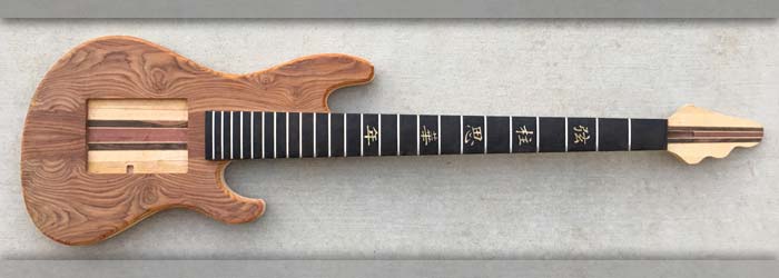
|
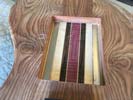
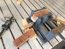
Slots for magnets have been machined. I'll get them installed asap!.
|
Left: Both channels have now been machined into the body to hold the two magnetic bars. Now I will get them glued in there making sure the polarity is correctly matched. Right: Text and picture coming. |

Slots for magnets have been machined. I'll get them installed asap!.
|
|
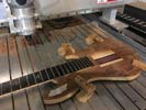
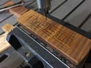
Getting ready to cut the slots for the magnet installation. Then I can glue on the matching plate.
|
Left: I have the bass body set up on the CNC so that I can cut the two recesses for the bar magnets. I will install the magnets and then glue the matching wood baseplate on top. Right: The positioning of the magnetic bars is fairly important so I have calculated what appears to be the best locations relative to pickups and will now cut slots. |
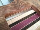
Once these slots are cut I can get the two bars secured into the body material..
|
|
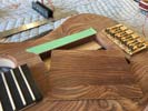
Ended up taking quite a bit of material off the plate but this looks like the right thickness to place the pickups a the correct height..
|
Left: This is the plate I ended up with after machining and sanding to size. I will now install the two bar magnets into the recess and this plate can then be fixed in place. Right: This is a rough idea of how I will be fitting out the bottoms of the pickups to include magnets and non-friction material so that they can be easily moved. |
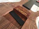
This is the basic plan for the baes of the two pickups. I can cut a substrate that will serve as a magnet holder and a sliding base.
|
|
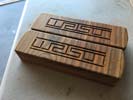
Logos cut and now a quick coat of sealer to do before I fill the recesses.
|
Left: Logo has been cut in the tops of the pickups and I will now coat them with a sealer so that the filler compound will not bleed into the grain of the wood. Right: After some calculation I decided that the pickup bases could be 3/16" above backplate allowing for felt + room for wiring to pass through. That gave me a back plate thickness. |
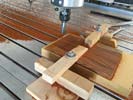
I'm rough machining the back plate to just over final thickness and I will finish on the drum sanded before installation.
|
|
I will be cutting the WG logo in the tops of each of these covers.
|
Left: Setting up to engrave logos on the tops of the two pickup covers. I need to get these cut and filled before this bass goes off to finishing. Right: I ran the program on one of the pickups and it looks good so I will continue with the second one. Once they are sanded I will seal the grin and then add a gold compound to fill the cut. |
Cutting the WG logo into the top surface of one of the pickup covers..
|
|
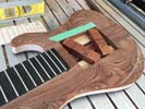
Got plenty of rotation and I think enough space between pickups and recess to allow them to move freely after finishing..
|
Left: I took as little as I could off these pickups to give them the freedom to rotate. We now will have even more flxibility on the positioning of the units on the finished instrument. Right: I'm checking the pickup height based on string height and the thickness of the back plate - I will have to reduce the back plate thickness a little. |
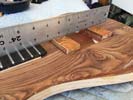
Since I need a little buildup on the back of the pickups for magnets I will need to reduce the back plate thickness a little to accommodate that - I suspected this would be necessary so I'm going to mill a little off the back face and re-test.
|
|
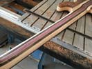
I'm in the process og grinding material off the neck thickness to achieve a nice thin profile. I will be sanding and shaping to refine and finish this.
|
Left: Working on the sizing of the back of the neck. I am shooting for a pretty thin profile neck section with something between a C and D shape curve on the back. Getting closer. Right: Cut the modified pickup shape in the laser so that I could check its rotation. Actually rotated more than I intended but finish will add some thickness. |
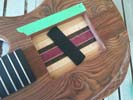
I think I will go with this profile because I will have surface finish both on the pickups and on the recess so this shape will most likely work just about right!.
|
|
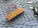
This is an artist rendering right now but as soon as I can get it on the machine I will cut the artwork and fill it with gold glitter.
|
Left: I am getting the logo artwork ready to cut into the tops of the pickups. May do that with the laser engraver. We plan to fill the logo with a gold glitter. Right: I am adapting the pickup covers so that they can rotate a little and be as flexible as possible in their positioning. Also working on a felt based soltion under the magnets. |
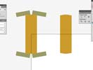
Before I started removing materials from the pickups I wanted to test a modified geometry in the pickups cavity itself. To that end I drew up a modified profile wich I will cut from spare material, test and it it works (as expected) I will apply that geometry to the pickups.
|
|

Cable channel done to the best estimate I can make right now - should be OK though.
|
Left: Next challenge is to compare pickup depth to recess depth and calculate the thickness of the cocobolo back plate that we will be installing. Pickups need to end up at the right height for the strings. Right: Working on several things. One of them is that we will have Watson logos on the tops of the pickups in gold lettering. |
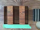
I'm going to be etching the logo into each of these pickups and filling with a gold compound. The wood color will resolve to match the body - the color difference is just because I have been sanding these!.
|
|

Nice to get the holes done for the tuners. I'll do a little cleanup on the headstock shape but otherwise it's ready in this area for sanding.
|
Left: I got the tuner holes drilled into the headstock which helps move things along with this instrument. Need to now clean out recess for the truss rod lid. Right: This is the end result of me cutting the little cable channel in the pickup recess. Not really much to see but I hope it does its job in housing the cables from the moving pickups. |
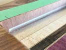
Cable channel done to the best estimate I can make right now - should be OK though.
|
|

I have calculated the furthest the wires will need clearance based on their range of motion and I will cut a channel to match that area. I want to keep the wiring as discrete as possible on the finished product.
|
Left: I decided to get the instrument up on CNC and machine out a suitable channel running right along the base of the recess on the lower side for pickup cabling. Right: I'm using a small T-cutter to cut a little channel at the bottom side of the pickup recess which is designed for the cabling to nest into when we are done. |
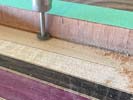
Cutting a little channel in the recess for the cables going to the control cavity.
|
|

Working on the bridge pickup cover right now - then I will do the same to the neck pickup cover.
|
Left: In order to test the fitting of all the parts I need to finish the pickup covers by machining out the internal recesses so that the bobbins fit inside them. Right: Both covers machined and pickups fit in there just fine. Glad I did this because it gives me a better perspective on the overall pickup depth and requires recess depth! |

We now have pickup assemblies and I can use the net height on these to finalize some of the other dimensions.
|
|

Hadding some decorative veneer to the sides of the pickup recess.
|
Left: After much deliberation I decided to install the veneer to give the recess a nice clean look. I can cut channels for wiring after this is done. Breaking new ground here! Right: Working on getting the inside trim attached to the sides of the recess so that I can move on to getting the wire slot cut and then the back plate installed. |

Almost done with the recess work.
|
|

More aesthetic than functional but I think the white line would be distracting on the finished instrument.
|
Left: I'm going to apply a veneer of matching wood around the recessed edge of the pickup cavity to blend and hide the line of maple that is exposed around the inner egdes. Right: I'm also trying to create a slot along the bottom of the pickup recess so that the cables from the pickups can run cleanly to the control cavity. More on this coming. |

Lots of thought and planning going into the design of this pickup recess..
|
|

Gluing headstock plate onto headstock. It will look really nice when done.
|
Left: The Cocobolo headplate is now being glued onto the headstock. After the glue is set I will clean up the headstock shape and can get tuner holes drilled. Right: Headplate now part of the instrument and I will now get it sanded to the finished headstock shape. Once that's done I will be able to establish the tuner holes. |

Headplate is now attached to headstock.
|
|

Once the truss rod cover is cyut out I will glue this onto headstock and trim to final shape.
|
Left: The headplate has been sanded a good bit closer to the headstock shape and I will now be cutting out the truss rod access cover. Once that's done the plate can be attached. Right: Setting headplate up on CNC so that I can harvest out the truss rod cover. I want to get this done so that I can attach the headplate to the headstock! |

Got the russ rod cover cut out of the headplate so I can assemble to the neck now.
|
|

Thicknessing a chunk of Cocobolo for the headstock cover plate.
|
Left: I had a very nicely figured piece of Cocobolo saved for the headstock front plate. In this photo I am milling it down from a rough sawn piece to a thickness I can sand. Right: It's a little oversize for the headstock but I did sand it down to just about the righ thickness. This means I can trim it to size, square the end and cut truss rod cover. |

I will cut this to seze and it will look awesome on the headsock.
|
|

As far as I can tell I am done with milling the recess.
|
Left: I cut the recess to what I think will work for depth. I need to compare with bridge and pickup covers in place and if it looks ok I will move on. Right: I'm setting up the back plate so that I can cut the slots for the bar magnets. I just had to be careful that their positions matched the anticipated placement of the magnets in the pickups. |

As far as I can tell I am done with milling the recess.
|
|

Machining the pickup recess - will have to be pretty accurate with the final depth!.
|
Left: I now have the bass up on the cnc to cut out the material to create the pickup recess. I will use the pickups and the backplate to asess the best depth. Right: I'm checking the depth of the pickup recess against the string height and pickup height so that I can get all these variables to work together. Almost there. |

The recess has to be just the right depth for the pickup after the back plate goes in.
|
|

Outsides of pickups are machined - now I need to trim them to height and do another machining operation to hollow out the insides.
|
Left: I machined the two pickups so that the outside dimensions are final. The wood changes color when machined but will soon return to an even color. Right: A quick photo of the pickups on the body - all the colors will resolve to the same tones. I'm going to cut the recess so that the pickups are nested in at the right height. |

I need to get the body up on the cnc and machine out that rectangular recess deep enough to place the back plate with the bar magnets in there..
|
|

These bar magnets are strong enough to work as holding devices behind the wood. I tried it with regular steel bars and it just wasn't quite strong enough to safely retain the pickups. I will be machining the slots and embedding these in place to line up with the magnets on the pickup covers.
|
Left: I am setting up to cut two slots in the back of the plate that will support the pickups. I want to make sure the new magnets will align with those on the pickup covers. Right: Setting up to do some machining on the pickup covers. I will be machining outside and inside so that I can fit the bobbins into each of them. |

I will first machine the outside oerimeter of both pickups, and once they are sanded I will amachine the insides.
|
|

Custom pickups for this bass and all hand made - they should be nice and hot and produce great tone.
|
Left: Pickup bobbins have been wound and will now be potted after which they will be complete and ready for action. Great to get these done. Right: Pickups have now been potted and are complete and functional. I will be cutting the recesses in the back of the pickup covers so that I can get these fitted prior to finishing. |

Great to get the two pickups completed. One of my next tasks will be to finish the covers so that the bobbins fit nicely inside.
|
|

Pickup cover blanks ready for machining to size.
|
Left: These are now the pickup cover blanks. I will machine these to a finished external size which will fit inside the pickup recess on the top. Right: These are the neo bar magnets I ordered for the back of the pickup recess. They are just the right length and should provide the right amount of grip for the two pickups. |

This is a new venture for me but I see no reason why this would not be the perfect solution for achieving the right stability for the two pickups.
|
|

MI will be ordering these magnets to embed into the back of the wood insert for the pickup cavity. Four od these will create two tracks onto which the magnets in the pickups will be attracted.
|
Left: After a lot of research and experimenting it looks like I will need to embed linear magnetized strips under the wood at the bottom of the pickup recess to get the right amount of grip. Right: Clamping the top pieces for the two pickups onto material that will be the body of the pickups. Once this is done I will machine them both to size. |

Gluing the pieces of the pickup covers together. These will be machined into a beautiful pair that will complement the instrument.
|
|

Must have taken half a pount of hardwood of this bass but the benefot is that I can test it's feel and fit better as I bring all these sizes into a finished profile.
|
Left: Rough grinding a lot of material off the neck of the neck and in the neck joint area. I will move to sanding on the neck soon, this helps with finalizing body contour and shape. Right: More work done on the back of the neck, the neck joint and also now have the makings of a very nice looking belly cut on the back of the body. |

More work on the back where the comfort and fit of the instrument are being considered.
|
|

Tjis flatwork has holes for magnets and terminals for the copper wire and is made from a special composite.
|
Left: Pickup bobbin blanks have been cut out on the laser and they are now ready to have magnets installed. Once that's done they'll go off to get copper wire wound. Right: I have assembled the flatwork with 5 pairs of magnets each to create the bobbins. Now that these are assembled I can have them wound with copper wire. |

Pickup bobbins have been assembled and are ready for winding.
|
|

Pole placement is very important and I will be using 3/16 neo magnets to make sure the pickups stick quite solidly to the base of the recess.
|
Left: Time to get the pickup bobbins made. I want to make the pickups wide enough for a healthy amount of copper but narrow enough to maximize placement. Right: I have drawn up the pickup bobbin geometry and can transfer that to a file where I can cut these on the laser. Once they are cut I will assemble with magnets and have them wound. |

Flatwork for pickups has been designed and saved in a format that my laser can read. I'll get the bobbins cut next.
|
|

This is the bass right after the top was glued on.
|
Left: I made several checks on alignment and positioning before committing to gluing the top plate onto the rest of the instrument. Looking good already! Right: This material is being cut for the matching pickup covers in the bass. I am using bookmatched material that will closely match that of the back of the recess. |

These are the cocobolo pieces that will become the tops of the two floating pickups.
|
|

Always a rush job because one you apply the glue you only have a fen minutes to get everything set, aligned, into the bag and wait for the air to evacuate!.
|
Left: All the frets are dressed and threfore not a threat to the vacuum press (don't want shart edges in there) so I have added adhesives and the top is now being attached to the body. Right: Did some more spindle sanding around the perimeter of the body to get much closer to the finished profile of the body. Moving on.. |

Body shape pretty much cut to size - will now do some work on the back of the neck and body.
|
|

MNaking ure I have created enough relief under the top plate for a good fit!.
|
Left: Having filled the spaces around all the fiber optics I can now double check fit of top plate and make sure surface are ready for attaching the top plate. Right: Before gluing on the top plate I'm taking the opportunity to file and dress the fret ends which is much easier to do without the top taking up vertical space! |

Dressing fret ends before the attachment of the board.
|
|

As soon as I have all the fibers through to the control cavity I will pot the rest of the channel and get the top plate attached!.
|
Left: I usually try to bend and glue two fibers at a time - more than that and it can get a little tricky! I have about half of them routed through so will soon be finished with this task. Right: Just a quick photo to show the process of potting the fibers so that they are safe and solid inside the innstrument. Almost done with this process. |

Potting going well - one more application and this will be done.
|
|

Gluing of fingerboard came out well and that's a big job behind us now!.
|
Left: Fingerboard is now permanently attached to the neck of the bass and all went wekk in the gluing process. I now have to get these strands of fiber optics under control. Right: Time to get these fiber optic cables under control. I need to carefully heat bend them and transfer them through the slot I cut to the control cavity. |

I can only do a couple of fibers at a time as I have to individually bend them. I'm routing them all along our little recess and gluing them in as I go.
|
|

Getting all my glues and tools and supplied ready for attaching fingerboard.
|
Left: Got all my gluing apparatus ready for doing the fingerboard glue-up. I need to have everything I could possibly need within arms reach when I start so preparation is half the job. Right: The fingerboard is now being glued to the neck of the bass. This will allow me to get all the fiber optics routed through to the back of the body. |

Fingerboard is being glued to the bneck of the instrument.
|
|

I need to get the fingerboard attached to the neck so I'm adding some sealer to the top surface to provide some protection.
|
Left: I'm giving the fingerboard a couple of protective sealer coats before I get it attached to the neck of the bass. It works good for contrast but it helps with protection too. Right: I spent some time building up the area on the fingerboard where the fiber optics leave the neck. Also heat bent the fibers to go round the corner! |

Fiber optic cables being carefully bent to get them running in the right general direction!.
|
|

Spent a little time working on the body perimeter.
|
Left: Doing a little refinement on the body perimeter (and also top plate) so that they match each other. Trying to get everything prepared for top & FB going on! Right: I am getting the two continuous grain covers ready to fit on the back cavities - need to reduce their thickness. Also looking at body edge breaks and belly cut. |

Lots of little tasks to do to the body while I am busy pre bending fiber optics and getting material ready for pickup covers.
|
|

I want to get these wiring chennels in so that I can start assembling fingerboard and top plate.
|
Left: The bass is now up on the CNC where I am going to machine a few channels in the top surface that will become my wiring channels after the top plate goes on! Right: Machining done! I now have the required wiring slots in the top of the body and can move ahead and plan for attaching the fingerboard and the top plate! |

Wiring slots have been machined into the top of the body.
|
|

Both cavities in the back of the bass have now been machined.
|
Left: I have now machined both the control cavity and the battery cavity into the back of the instrument. This is a big move forward in getting this bass ready for finishing! Right: Marking out all the areas I need to machine wiring holes. I will get this done on the CNC very soon and have also decided Hipshot bridge fits best on this bass. |

Marking the top for upcoming work creating wiring channels.
|
|

PThe top plate needs to be attached because the cavity will extend slightly into the back of the top.
|
Left: Bass is now set up level and squate to the machine axes and I'm ready to get the back recesses cut. I'm doing this with front face temporarily attached. Right: I am in the middle of machining the control cavity. In the process of machining you can see that we also expose the channel for the fiber optic cables. |

Right in the moddle of machining the control cavity.
|
|

Will be cutting two pockets on the back on the CNC.
|
Left: I'm just about to put this bass on the CNC so that I can cut out the battery and the control cavities. Once they are done I have somewhere to run the fibers into!. Right: Program for cutting the control cavity is prepped so I am going to do that part first. I'll be setting the bass up on the CNC to do control and battery cavities. |

Programming done - now to cut some wood!.
|
|

The top plate now have the pickup recess cut out and I can move ahead and get things ready for fingerboard and top plate assembly!.
|
Left: The rectangular section for the pickup recess has been harvested out of the top plate of the bass. I now have to machine a channel for the pickup wires. Right: I'm finishing up some details on the fingerboard and before I attach it I will flip the bass over and machine control cavity and battery cavity into the back! |

Next operations will be on CNC to cut both back cavities.
|
|

Ready to make the cuts and remove the section from the top plate that will be replaced once the pickup recess has been cut.
|
Left: I'm setting up the top plate on the CNC so that I can harvest out the top plate section that will ultimately sit behind the pickups. Only oen chance to do it right!!!. Right: First cut is done which takes me about 3/4 through the material with that tiny cutter. Now have to finish the cutting from the back side! |

I can only cut about 1/4 inch deep with the small end mill so I will fixture the top and finsh the cut from the back side..
|
|

I may be able to slightly reduce the width of this cutout based on which magnets I decide to use. Right now 3/16 diameter seems to make most sense so I am allowing for that.
|
Left: This is the approximate size of the recess section for the two pickups based on pickup height calculations. Pretty much standard for pickup dimensions. Right: Here are some final dimensional drawings of the top plate cut out and the pickups that will be going in there. 1/8 neo magnets should do a fine job of holding them in place. |

I'm making decisions on several things before committing to cutting the top but I think this will do the trick and I will go ahead and get the components cut.
|
|

The cutout of the top plate has to be done pretty carefully and accurately. I plan to use a .037" diameter end mill to minimize any material loss. Should work out fine.
|
Left: I am establishing the dimensions of the cutout for the top plate. It will happen in two separate operations as I have to use a super small diameter cutter. Right: I have drawn the limits of the pickup cutout and now I will get a program written to harvest out the top material. The cut out will be used as an insert below the pickups. |

I'm deciding on the extent of the cut out based on the anticip[ated width of the pickups and the linear adjustment length.
|
|

Taking some critical measurements so that I can set up for cutting the recess for the pickups.
|
Left: This photo shows me where the end of the fingerboard and the bridge will be placed relative to each other This allows me to plan the cutting of the recess in which the pickups will live. Right: Marking out the top plate so that I can get it set up on the cnc and get the cutting of the pickups recess started!!!. |

The pickups will not have traditional adjustment screws so I am designing them based on coil requirements and string spacing. I'm being careful to arrive at the best possible combined geometry.
|
|

Top plate up on the CNC and I am machining what I intend to be a perfect fit for the top plate and the neck of the bass.
|
Left: Currently machining the top plate so that I can get a perfect fit for the top plate around the neck. Once this is done I will be able to plot the extent of the pickup recess and can cut that area out too. Right: Now that the top fits I can refine body shape and get those fiber optic cables to fit the channel I cut for them! |

Next immediate task is to get the fiber optic cables slightly heat bent so that they will filloe the curve of the channel I cut for them in the body.
|
|

Did some grinding behind the truss rod to create a little clearance for the fiber optic cable.
|
Left: Now that I have the F/O channel cut I needed to do some fiber cable relief under the fingerboard at the end of the neck so that the cables can exit properly. Right: I'm getting realy to cut out the neck relief in the top plate so that I can have it positioned and cleaned up on the perimeter. Then I will cut pickup recess. |

PSome final fitting tasks before I joing the fingerboard to the neck of the bass.
|
|

Getting my grinder into the job of roughing off the unwanted core material where the neck and body overlap.
|
Left: I sawed off extra material at the bottom of the body and I'm also working on grinding the back of the neck through the forware body area. Right: I'm working on the last few details before I fit the fingerboard to the neck of the bass. Fibers need to be routed to fiber channel and back of neck needs to be roughed out a little more. |

PSome final fitting tasks before I joing the fingerboard to the neck of the bass.
|
|

I need to get the fiber optic cables to turn as sharp a corner as possible so that I keep the maximum space available for the pickup recess.
|
Left: This is how the fiber optic channel worked out combined with the forward limit of the pickup recess. Should work out fine. Right: I now have the body set up on the CNC to cut out the channel for the fiber optic cables. I will keep it as narrow as possible to allow maximum travel for the sliding pickup area. |

This operation is to machine a channel for the fiber optic cabling.
|
|

